protech HDP-2000 Operating Instructions Manual
Hide thumbs
Also See for HDP-2000:
- Operating instructions manual (40 pages) ,
- Operating instructions manual (42 pages)
Table of Contents
Advertisement
Available languages
Available languages
Quick Links
Advertisement
Table of Contents

Related Manuals for protech HDP-2000


Summary of Contents for protech HDP-2000
- Page 1 HDP-2000 Teleprompter ポータブルスタジオテレプロンプター HDP-2000F HDP-1500 HDP-1500F Operating Instructions Before operating the system, please read this manual thoroughly and remain it for future reference. 取 扱 説 明 書 ご使用の前に必ずこの取扱説明書をお読みください。 なお、 取扱説明書は必要に応じてご覧になれるよう 大切に保管してください。 Ver. 1 . 1 . 1...
- Page 2 安全上の注意 WARNING この製品の使用、 または使用不能から生ずる付随的な損害(情報内容の変化 ・ 消失、 事業利益の損失、 事業の 中断など)に関して、 当社は責任を負いかねますのであらかじめご了承ください。 取扱説明書の記載内容を守らないこと、 あるいは取扱説明書の記載内容の誤記、 等により生じた損害に関して、 当社は責任を負いかねますのであらかじめご了承ください。 ご使用の前に、 この 『安全上の注意』 をよくお読みのうえ、 正しくお使いください。 また、 お読みになった後は、 大切に保管してください。 安全上の注意は、 お使いになる人や、 他の人への危害、 財産への損害を未然に防ぐための内容になっています ので、 必ずお守りください。 表示と図記号の意味は次のようになっています。 警告 “ 取扱いを誤った場 合 、 使用者が死亡または重傷を負うことが想定されること”を示します。 ■煙が出ている、 変なにおいや音がする等の異常が発生した場合は、 電源スイッチを切る! ■本 機を落としたり、 強い衝 撃を与えたり、 破損した場合は、 電源スイッチを切る! ■本機の内部に水などが入った場...
-
Page 3: Table Of Contents
目次 Table of contents Teleprompter HDP-2000/2000F/1500/1500F Names and Functions of Parts - - - - - - - - - - - - - - - - - - - - - - - - - - - - - - - - - - - - - - - - - - - - - - - - - - - - - - - - - - - - - - - - - - - - - - - - - - - - - - - - - - - - - - - - - - - - - - - - - - - - - - - - - - - - - - - - - - - 4... -
Page 4: 各部名称と働き
Parts Names and Functions 各部名称と働き Teleprompter HDP-2000/2000F /1500/1500F 各部名称と働き Front Panel 前面パネル HDP-2000/2000F HDP-1500/1500F 天板固定金具および取っ手 Top board fastening hasp and Handle Used to fasten the top board with the mirror and shading cover built-in. When carrying, be sure to fasten the top board with the fastening hasp. ハー フミラーが内蔵された天板を閉じ、 固定します。 取っ手を持って移動する時には、 天板は必ず天板固定金具で固定してください。 Rubber feet ゴム足 It enables to put the HDP-2000/1500 main body on the desk or floor. 本体を机上、 床上に置く ことができます。 Tally lamp タリーランプ For HDP-1500/1500F only It lights in RED by the TALLY signal input to the TALLY connector. TALLYコネクタへ入力されるタリー信号により点灯(赤のみ)します。... -
Page 5: Left Side Panel
Teleprompter HDP-2000/2000F 1500/1500F 各部名称と働き Left side panel 左面パネル 天板ロックツマミ Top board lock knobs (left and right) Used to lock the top board opened. ハー フミラー (天板) を開いて、 このツマミで固定します。 Top board 天板 The half mirror and the shading cover are installed. ハー フミラーおよび遮光カバーが取付けられています。 Shading cover 遮光カバー 上面 Put the end of the lens into the shading cover and narrow the mouth of it by the drawstring to shut out the light. カメラのレンズの先端を中に入れ、 口元を絞って外光を遮断します。... - Page 6 Teleprompter HDP-2000/2000F/1500/1500F 各部名称と働き Right side panel 右面パネル HD-SDI IN HD-SDI OUT TALLY HDMI PC IN VBS IN P B IN POWER DC IN TELEPROMPTER OFF ON 1 GND 4 +12V HDP-2000 NIPPON VIDEO SYSTEM CO.,LTD MADE IN JAPAN HD-SDI IN コネクタ (BNC) Used to input the HD-SDI signal to the prompter with the BNC cable. プロンプタにHD-SDI信号にて入力する場合、 BNCケーブルを接続します。 HD-SDI OUT コネクタ (BNC) Used to output the HD-SDI signal input to the HD-SDI IN. Connect to the external equipment with the BNC cable. HD-SDI IN に入力された信号を他の機器で使用する場合、 BNCケーブルを接続します。 TALLY IN コネクタ (BNC) Used to input the TALLY signal to light on the TALLY indicator of the prompter. プロンプターにタリーを点灯させる場合、 BNCケーブルを接続します。 Input signal Indication 表示 0 V OFF 2 V 〜 4 V GREEN TALLY lights on. 緑タリー ON 4 V 〜 5 V RED TALLY lights on. 赤タリー ON...
-
Page 7: Right Side Panel 右面パネル
Teleprompter HDP-2000/2000F/1500/1500F 各部名称と働き Right side panel 右面パネル HDMI IN コネクタ Used to input the HDMI signal to the prompter with the HDMI cable. プロンプタにHDMI信号にて入力する場合、 接続します。 PC IN コネクタ (D-sub 15ピン) PC IN Connector (HD D-sub 15-pin) Used to input the PC signal to the prompter with the HD D-sub 15-pin cable. プロンプタにPCから信号を入力する場合、 D-sub 15ピンケーブルで接続します。 VBS IN コネクタ (BNC) VBS IN Connector (BNC) Used to input the composite video signal to the prompter with the BNC cable. プロンプタにコンポジットビデオI信号にて入力する場合、 接続します。 PB IN コネクタ (8ピン) PB IN Connector (8ピン) When using the prompter connecting with the PC, used to connect with the PB Remote Controller PB-RM1A or PB-RM1B. Pressing the button of the PB Remote Controller changes the input signal from the PC IN signal to the HD-SDI IN signal. プロンプタをPC IN にて使用する場合、 リモコンPB-RM1Aを接続して操作します。 PB-RM1Aのスイ ッチを押すとHD-SDI IN(プレイバック/リターン信号を入力)に切り替ります。 POWER Switch POWER 電源スイッチ 本体の電源をON/OFFします。 Turns the power on or off. DC IN コネクタ (XLR 4P) DC IN Connector (XLR 4-pin) Used for connection to the AC adaptor(DC power supply) to supply power to the teleprompter. 本体へ電源を供給します。... -
Page 8: Operation Panel 操作パネル
Teleprompter HDP-2000/2000F/1500/1500F 各部名称と働き Operation panel 操作パネル 液晶画面 LCD Screen The display screen is 20 inches LCD. 20インチ液晶画面に表示します。... - Page 9 Teleprompter HDP-2000/2000F/1500/1500F 各部名称と働き Operation panel 操作パネル MENU / ▲ / ▼ buttons MENU / ▲ / ▼ スイ ッチ Pressing the the MENU button selects the menu and pressing ▲ / ▼ button adjusts and enters the each setting according to the display on the screen. When “Reset” is selected, pressing ▲ / ▼ button resets all to standard value(50). MENU と ▲ ▼ スイ ッチにより画面の明るさ等を調整します。 MENU button ▲ / ▼ (entry) button ↓ Brightness ( 0 - 50(reset) -100 ) ↓ Contrast ( 0 - 50(reset) -100 ) ↓ Peaking ( 0 - 50(reset) -100 ) ↓ Sharpness ( 0 - 50(reset) -100 ) ↓ Saturation ( 0 - 50(reset) -100 ) ↓ Hue ( 0 - 50(reset) -100 ) ↓ Reset ( Pressing resets all settings to “50” ) ↓ RED TALLY OFF/L/H /GREEN TALLY OFF/L/H Switch OFF/L/H スイ ッチ Set the TALLY indicator, RED TALLY / GREEN TALLY to OFF, L(Low) or H(High). RED TALLY, GREEN TALLY の表示をOFF:消灯/L:減光/H:点灯に切り替えます。 RED TALLY/GREEN TALLY Indicators RED TALLY/GREEN TALLY 表示 RED TALLY lights up when the tally signal, the voltage of 4 V to 5 V. GREEN TALLY lights up when the tally signal, the voltage of 2 V to 4 V. RED TALLY タリー入力信号 = 4 V 〜 5 V のとき 赤点灯 GREEN TALLY タリー入力信号 = 2 V 〜 4 V のとき 緑点灯 PC スイ ッチ...
- Page 10 Teleprompter HDP-2000/2000F/1500/1500F 各部名称と働き Operation panel 操作パネル HDMI スイ ッチ HDMI Switch Used to turn on the display of the HDMI input signal. HDMI IN 入力の信号の表示に切り替えます。 VBS Switch VBS スイ ッチ Used to turn on the display of the VBS IN input signal. VBS IN 入力の信号の表示に切り替えます。 (コンポジットビデオ信号) INVERT Switch INVERT スイ ッチ Used to invert the black and white of the display. プロンプターの表示を正像/鏡像に切り替えます。 PB IN Switch PB IN スイ ッチ Used for connection of the PB Remote Controller. When the PC IN input mode (The PC switch is ON.), while the PB IN switch is pressed, the display turns to the HD-SDI IN input signal image. (NOTE : It takes time a little before indication is replaced.) PC IN 入力に設定されている場合(PCスイ ッチが押されている場合)、 このスイ ッチが押されている間HD-SDI IN 入力の信号の表示に切り替わります。 (注意 : 表示が切り替わるまでに少し時間がかかります。 )
-
Page 11: Rear Panel And Bottom Panel
Teleprompter HDP-2000/2000F/1500/1500F 各部名称と働き Rear panel and Bottom panel 背面パネルおよび底面パネル Rear Bottom Screw holes for the camera plinth fixed カメラ台座固定用ネジ穴 Used to fasten the camera plinth to the teleprompter main body. 本体とカメラ台座を結合、 固定するネジを挿入するネジ穴です。 Guide rails for the camera plinth カメラ台座レール Used to fit the camera plinth to the teleprompter main body. Insert and slide the uniting board of the camera plinth along the groove of the rail until it is in place. レールのくぼみにカメラ台座の本体受板を挿入して本体を結合し、 ネジ(2本)で固定します。 Tripod socket screw hole, female, 1/4 inch. 三脚用ネジ穴 (1/4インチ) Used to mount the teleprompter alone on the tripod. プロンプタ本体のみを三脚にマウントする場合は、 このネジ穴を使用します。... -
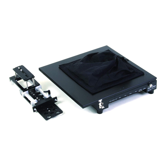
Page 12: Camera Plinth
Teleprompter HDP-2000/2000F/1500/1500F 各部名称と働き Camera Plinth カメラ台座 本体受板 Main body uniting board To unite the teleprompter with the camera plinth, this board is inserted in the camera plinth rail. プロンプタ本体とカメラ台座(スライドユニッ ト)を結合させる時本体を載せて支持します。 本体下面のレールに挿入します。 Main body fixing screw 本体-カメラ台座固定ネジ The main body of the teleprompter is fixed with this screw. プロンプタ本体とカメラ台座を結合し、 固定します。... - Page 13 Teleprompter HDP-2000/2000F HDP-2000/2000F 各部名称と働き Camera Plinth カメラ台座 Tripod mounting plate 三脚固定板 Used to fix the teleprompter to tripod stand. プロンプタ-カメラ台座を三脚に固定するネジ穴(1/4および3/8インチ)の開いた下板 Clamp 三脚固定板ロック金具 Used to tighten the plate of tripod. スライドする三脚固定板を任意の位置で固定するネジ金具 Camera mounting board カメラ固定板 Used to mount the camera or the tripod base(or tripod adaptor). プロンプタ-カメラ台座にカメラ,またはカメラを装着する三脚ベースを固定するための上板 Clamp カメラ固定板ロック金具 Used to tighten the camera mounting board in the appropriate position. カメラ固定板をスライドさせカメラの前後位置を自由に調整し固定するネジ金具 カメラ固定ネジ Camera fixing screw Used to tighten the camera or the tripod base. カメラまたはカメラを装着する三脚ベースを固定するネジ(3/8インチ,2個) Balance plate (Slide plate) バランスプレート (スライドプレート) When the small size or light weight camera is used, slide the balance plate forward to balance the weight of the camera and the teleprompter. 小型カメラの使用で重心が前方に来る場合に、 プロンプター本体とカメラがバランスする前方に 三脚プレートの位置を移動するためのプレートで、 本体受板と三脚固定板にネジで固定します。...
-
Page 14: Use 使用方法
使用方法 Use 使用方法 Teleprompter HDP-2000/2000F /1500/1500F Fixing 組み立て方法 1. When the small size or light weight camera is used, use the balance plate. Install the balance plate to the main body uniting board and the tripod mounting plate by the supplieded screws. Caution : Select the appropriate screw holes considering the balance of the weight of the camera and the teleprompter. 1. カメラが小型 ・ 軽量の場合または三脚プレートが小さい等の場合、 カメラ台座にバランスプレート を取付けて使用します。 カメラ台座の本体受板および三脚固定板に付属ネジにて固定します。 注意: バランスプレートを取付ける位置(ネジ穴)は、 カメラとテレ プロンプターの重量バランス考慮 してバランスプレートおよび三脚固定板の適切なネジ穴を選択してください。 Tripod mounting plate Main body uniting board 三脚固定板 本体受板 Balance plate バランスプレート 2. Fix the tripod plate to the camera plinth or the balance plate with the screws of tripod stand. 2. カメラ台座(バランスプレート)に、 使用する三脚プレートを三脚の付属のネジにて固定します。 Tripod plate 三脚プレート... -
Page 15: Fixing 組み立て方法
使用方法 Teleprompter HDP-2000/2000F /1500/1500F 組み立て方法 Fixing 3. Lock the tilt of tripod stand firmly, and mount the camera plinth to the tripod stand. 3. 三脚のチルトをしっかりと固定した後、 カメラ台座(バランスプレート)を三脚に固定します。 4. Attach the tripod base to the camera mounting plate of the camera plinth and secure it with the screws. 4. カメラを装着する三脚ベースをカメラ台座のカメラ固定板に付属のネジにてしっかりと固定します。... - Page 16 Teleprompter HDP-2000/2000F /1500/1500F 使用方法 組み立て方法 Fixing 5. Place the teleprompter main body on the main body uniting board of the camera plinth (Put the main body uniting board into the groove of the guide rail on the bottom of the teleprompter main body), and slide it into the depths of the rail until it stops. 5. プロンプタ本体をカメラ台座の本体受板に正しく載るように本体底部のレールに合わせてスライド させ、 挿入します。 Main body fixing sarews, left and right カメラ台座固定ネジ 6. Tighten the main body fixing screws to unite the main body and the plinth firmly. 6. プロンプタ本体とカメラ台座結合部のカメラ台座固定ネジ (2本) でしっかり固定します。 Main body fixing sarews, left and right カメラ台座固定ネジ...
- Page 17 使用方法 Teleprompter HDP-2000/2000F /1500/1500F Fixing 組み立て方法 7. Mount the camera to the tripod base on the camera plinth. And, loosen the cramps, slide the camera forward or backward until it is in the appropriate position, and tighten the cramps. Caution : The appropriate position is that the top of the lens is in the position a little ahead from the end of the main body. (from 0 cm up to approximately several centimeters) 7. カメラ台座三脚固定板の上の三脚ベースにカメラをマウントし、 ロックネジ金具をゆるめてカメラを 前後させ、 レンズの先端がプロンプタ本体の後端より少し前 (0〜数cm) になるようにして固定します。 several centimeters 8. Unlock the fastening in front of the main body, and open the top board. 8. プロンプタ本体正面の天板ロック金具をはずし天板を上げます。 Top board 天板 open...
- Page 18 使用方法 Teleprompter HDP-2000/2000F /1500/1500F 組み立て方法 Fixing 9. Fit the shading cover in the tip of the lens, and tighten the drawstring to close the opening of the shading cover. 9. 天板を上げた後、 遮光カバーがきちんとレンズ先端部分を包み込むようにかぶせ、 カバーの端の ひもを締めて遮光カバーを閉じるようにします。 shading cover 遮光カバー drawstring 絞りひも...
-
Page 19: Connection
使用方法 Teleprompter HDP-2000/2000F /1500/1500F 接続方法 Connection 1. Connect XLR 4P DC power cable to the DC IN connector on the main body. 1. プロンプタ本体に電源ケーブル(XLR 4P)を接続します。 POWER SW POWER cable 電源スイ ッチ 2. Connect the other end of the DC powere cable to the AC adaptor. 2. 電源ケーブル(XLR 4P)の他端をACアダプターに接続します。 POWER cable 電源ケーブル... - Page 20 使用方法 Teleprompter HDP-2000/2000F /1500/1500F Connection 接続方法 3. Connect the cables to input and display the signals. Connect the PC IN connector of HDP-2000F/1500F to the PC by the D-sub 15-pin cable. When displaying the HD-SDI play back signal, input the playback signal to the HD-SDI IN connector by the BNC cable. And connect the HDP-RM1A to the PB IN connector (8-pin). 3. プロンプタに表示させる信号ケーブルを接続します。 HDP-2000F/1500Fの PC INコネクタとPCとをD-sub 15ピンケーブルで接続します。 プレイバック(HD-SDI信号)を表示する場合は、 HD-SDI INコネクタにBNCケーブルで接続して HD-SDI信号を入力します。 また、 PB INコネクタにHDP-RM1Aを接続します(8ピンケーブル)。 4. Connect the PC IN connector of the HDP-2000F/1500F to the Proma PC with the HD D-sub 15-pin cable. 4. 本体の PC IN から 付属のHD D-sub 15ピンケーブルで プローマPCへ接続します。 Playback HD-SDI signal プレイバック用 HD-SDI 信号 HD-SDI IN HD-SDI IN HD-SDI OUT TALLY H D M I PC IN VBS IN P B IN POWER DC IN OFF ON 1 GND 4 +12V PB IN DC IN PC IN 8-pin...
- Page 21 HDP-2000/2000F 使用方法 Teleprompter HDP-2000/2000F Connection 接続方法 5. When using a manuscript imaging camera, connect it to HDP-2000/1500: to HDMI connector by a HDMI cable, or to HD-SDI IN or VBS IN connector by a BNC cable. 5. 原稿書画カメラを使用する場合は、 HD-SDI IN, VBS IN コネクタにBNCケーブルで、 または、 HDMI コネクタにHDMIケーブルで接続します。 Manuscript imaging camera 原稿用カメラ HD-SDI HDMI Composite HD-SDI IN HD-SDI OUT TALLY HDMI PC IN VBS IN P B IN POWER DC IN TELEPROMPTER OFF ON 1 GND 4 +12V HDP-2000 NIPPON VIDEO SYSTEM CO.,LTD MADE IN JAPAN HDP-2000 or HDP-1500 HD-SDI IN HDMI VBS IN...
- Page 22 Setting 設定方法 Teleprompter HDP-2000/2000F /1500/1500F 設定方法 画面の設定 Display 1. After connecting, turn on to supply the power to HDP-2000/1500 main body, the PC and the others and the image is displayed on the screen. According to the input image source, select the INPUT select switch. (NOTE) When using a PC and its software, please operate them according to their instruction manuals. For Proma soft usersʼ guide, see page 27-34. 1. 接続した後電源をONします。 しばらくするとモニター(液晶画面)に出画されます。 (注) PCおよびソフトを使用される場合はそちらの取説に従って操作して下さい。 Promaソフトユーザーズガイド,27〜34ページをご覧ください。...
-
Page 23: 設定方法
Teleprompter HDP-2000/2000F /1500/1500F 設定方法 Display 画面の設定 2. INPUT Select : Press the INPUT select switch according to the input signal. MENU Setting : Press the MENU switch to adjust the folloeings of the display: Brightness 液晶画面の明るさ Contrast コントラスト Color カラー Sharpness シャープネス Aspect ratio アスペクト比 2. INPUT 入力選択 : INPUT 選択スイッチを入力信号に合わせて押します。 MENU メニュー設定 : MENU ▲ ▼スイッチで、液晶画面の明るさ,コントラスト カラー、シャープネス、アスペクト比 を設定します。 PC HD-SDI HDMI VBS INPUT Select Switch MENU ▲ ▼ Switches 入力選択スイッチ PC/PB(HD-SDI) HD-SDI IN HD-SDI OUT TALLY HDMI PC IN VBS IN P B IN POWER DC IN TELEPROMPTER OFF ON 1 GND 4 +12V HDP-2000 NIPPON VIDEO SYSTEM CO.,LTD MADE IN JAPAN HDP-2000 or HDP-1500 HD-SDI input H DM I VBS ... -
Page 24: Camera Setting カメラの設定
Teleprompter HDP-2000/2000F /1500/1500F 設定方法 Camera Setting カメラの設定 1. Adjust the camera position by the tripod adjusting so that the camera can image the announcer properly and the announcer can read the manuscript on the screen properly. 1. カメラの位置、 アングル等を三脚を調節して設定します。 アナウンサーがカメラに正しく映るように、 アナウンサーが原稿を正しく読めるように調節します。 announcer アナウンサー manuscript image 原稿画像... - Page 25 Teleprompter HDP-2000/2000F /1500/1500F 設定方法 Camera Setting カメラの設定 2. Set the manuscript imaging camera and press the INPUT select switch according to the input signal. And adjust the position of the camera to make it easy to read the manuscript. 2. 原稿用カメラを正しくセッティングし、 原稿が読みやすく表示できるようにします。 Manuscript imaging camera 原稿用カメラ manuscript 原稿 to read the manuscript HD-SDI IN HD-SDI OUT TALLY HDMI PC IN VBS IN P B IN POWER DC IN TELEPROMPTER OFF ON 1 GND 4 +12V HDP-2000 NIPPON VIDEO SYSTEM CO.,LTD MADE IN JAPAN Composite HD-SDI HDMI manuscript image 原稿画像信号 INPUT Select Switch PC/PB(HD-SDI) HD-SDI IN HDMI VBS IN...
-
Page 26: Tally Setting
Teleprompter HDP-2000/2000F /1500/1500F 設定方法 TALLY Setting TALLY の設定 1. TALLY Setting : Set the RED TALLY/GREEN TALLY switch to H, L or OFF. 1. TALLY の設定 : RED TALLY/GREEN TALLY スイッチを必要に応じて切り替えます。 TALLY Select Switches TALLY Indicators RED GREEN RED TALLY GREEN TALLY OFF/L/H OFF/L/H PC/PB(HD-SDI) HD-SDI IN HD-SDI OUT TALLY HDMI PC IN VBS IN P B IN POWER DC IN TELEPROMPTER OFF ON 1 GND 4 +12V HDP-2000 NIPPON VIDEO SYSTEM CO.,LTD MADE IN JAPAN TALLY signal 2. Input the TALLY signal to light on the TALLY indicator of the teleprompter. Input signal Indication 表示 0 V OFF 消灯 2 V 〜 4 V GREEN TALLY lights on. 緑 点灯 4 V 〜 5 V RED TALLY lights on. 赤 点灯 2. TALLY信号を入力して TALLY表示が正しくされることを確認します。 * HDP-1500/1500F is equipped with the FRONT TALLY(Red tally only). * HDP-1500/1500F はFRONT TALLY(レッドタリーのみ)を装備しています。 FRONT TALLY... -
Page 27: Promaソフト ユーザーズガイド
Promaソフト ユーザーズガイド... - Page 28 プローマPCの電源ボタンを押して起動します プローマPCの電源ボタンを押すと、Promaソフトが起動します。 画面の説明 1. 原稿セット新規作成 3. 原稿セットの一覧 2. 原稿セットの削除 4. 原稿ボックス NEW DELETE ▼ 速度 Font 行間 A = ON AIR 10. オンエア 5. 速度 6. フォント 7. 行間 8. 表示モード 9. 横書/縦書 1. NEW (原稿セッ ト新規作成) : 原稿セッ トを新しく作成します。 2. DELETE (原稿セッ ト削除) : 現在表示している原稿セットを削除します。 3. (保存原稿セット一覧表) : 保存されている原稿セットのリストです。 4. 1 - 9 (原稿ボックス) : 原稿を格納します。 9つの原稿ボックスに別れています。 5. 速度 : 実行速度(スクロール速度)を15段階に設定出来ます。 (この画面では設定の...
- Page 29 原稿セットを作成します 1. [ NEW ]をクリックして、原稿セット入力画面にします。(下図の画面) 2. 原稿セットの名称を入力します。 3. 任意の名称を入力して、「OK」をクリックします。 4. 原稿セット中の既に作成された原稿セットを呼び出す場合は、▼をクリックします。 5. 原稿を入力する原稿ボックスを表示します。 原稿ボックスを表示する場合は、画面上の原稿ボックスをクリックするかまたは キーボードの数字キー(原稿ボックスのナンバー)を押します。 1. 新規原稿セットの作成 / NEW をクリック 4. 原稿セットの一覧 NEW DELETE ▼ 2. 原稿セットの名前を入力 原稿セット入力 原稿名称を入力してください キャ ンセル OK 3. 「OK」をクリック 速度 Font 行間 A = ON AIR 原稿セットとは 9つの原稿ボックスを束ねた1つのファイルです。9つの原稿ボックスにそれぞれ 異なる原稿を格納して、表示したい原稿をボタン1つで呼び出すことができます。 また、原稿セットはいくつも作成することができます。 用途や目的に応じて複数のセットを使い分けて、テキストを保存することができます。...
- Page 30 原稿 ボックスを作成します 1. 原稿セットには9つの原稿ボックスがあります。 画面1〜9の原稿ボックスをクリックして、タイトルと本文入力画面を表示します。 または、原稿ボックスナンバーの数字キーを押しと表示します。 2. Promaで表示/スクロールしたい文章およびタイトルを入力します。 3. 入力が完了したら、画面右下の「OK」をクリックします。 1. 原稿ボックスを表示します 2. 原稿ボックスのタイトル 2. 文章本文(記事) NEW DELETE ▼ 速度 Font 行間 A = ON AIR ※ この画面から ON AIR画面へ ; こちらをクリック 3.「OK」をクリック 他のパソコンで作成した内容を読むための方法 他のPCで作成した原稿のテキストデータを USBメモリー等のメディ アに保存し、 プローマPCへ移動します。 プローマPCへ読み込まれたテキストデータを コピー&ペーストで原稿ボックスへコピーします。...
- Page 31 実行ウインドウを開きます 1. 実行ウインドウを開きます。 1-1. 原稿セット画面で ON AIR をクリックする : 実行ウインドウ画面が開き、 最終開いていた原稿ボックスの原稿が表示されます。 1-2. 原稿ボックス画面で ON AIR をクリックする : 実行ウインドウ画面が開き、 原稿ボックスの原稿が表示されます。 1-3. 原稿セット画面で 1 〜 9 数字キーを押す : 実行ウインドウ画面が開き、 1〜9原稿ボックスの原稿が表示されます。 1-4. 原稿セット画面で コントローラの 1 〜 9 数字キーを押す : 実行ウインドウ 画面が開き、1 〜 9原稿ボックスの原稿が表示されます。 2. 実行/スクロールする原稿を選択/変更します。 実行ウインドウ画面で 1 〜 9 数字キーを押すとその原稿が表示されます。 (キーボードまたはコントローラいずれでも) 3-1. PCキーボードで実行/スクロール 3-1-1. (実行/スクロール) → キー を押す : 停止中に押すとスタートします。 実行(スクロール)中に押すと停止します。 3-1-2. (原稿TOPに RETURN) ← キー を押す : 停止中に押すとTOPに戻ります。 3-1-3. (原稿セット画面に戻る) Z キー を押す : 停止中に押すと原稿セット画面に戻ります。 3-2. コントローラで実行/スクロール 3-2-1. (実行/スクロール) START/STOP キー を押す : スタート/停止します。 3-2-2. (原稿TOPに RETURN) RETURN キー を押す : 停止中に押すとTOPに戻ります。 3-2-3. (原稿セット画面に戻る) 戻る キー を押す : 停止中に押すと原稿セット画面に 戻ります。 コントローラ 1 〜 9数字キーに原稿ボックスが割り当てられています。 キーを押すと、そのナンバーの原稿ボックスが呼び出されます。 キーボード 拡 大 背 景/ 文字 色 ...
- Page 32 実行ウインドウを開きます ▲ ■:停止/TOP(文頭) ●:実行/スクロール中 原稿ボックス 実行状態 || : 一時停止(途中または文末) ▼ 1 速度 1 Font 36 行間 100 A || ▲ ▼ ▲ ▼ ▲ ▼ BACK 速度 ▲ ▼ Font ▲ ▼ 表示モード A / A 行間 ▲ ▼ 実行ウインドウ/表示スタイルを設定します。 1. 速度 : 実行/スクロールする速度 1 - 10 実行/スクロールする速度を調節できます。 ▲/▼ をクリックして調節します。 2. Font : 文字サイズ 36 - 96 (31段階) 表示する文字の大きさを選択できます。 ▲/▼ をクリックして拡大/縮小します。 コントローラの文字サイズ-拡大/縮小 キー で拡大/縮小できます。 3. 行間 : 改行の間隔 30 - 150 (13段階) 拡 大 背 景 / 文 字 色 | 切 替 改行のペースを調節できます。 ...
- Page 33 実行ウインドウ/表示スタイルの設定 : キーボードの対応するキーで操作できます。 操作/対応キー (実行/スクロール停止中) (実行/スクロール中) 原稿ボックスナンバーを選択。選択された原稿の実行 原稿ボックス選択 1〜9 ウインドウが画面に表示される。 [文字:黒 背景:白] 表示モード切替 D 実行ウインドウ表示時操作可 [文字:白 背景:黒] 文字サイズ拡大 S 36から96ポイントまで2ポイントごと拡大 文字サイズ縮小 A 36から96ポイントまで2ポイントごと縮小 行間拡大 C 実行/スクロールが停止 した状態で操作可能 (可変範囲: 30〜150) 行間縮小 X 速度を上げる C 実行/スクロールしている 状態で操作可能 (可変範囲: 1〜15) 速度を下げる X 行を進める L 半行ずつ進む 行を戻す P 半行ずつ戻る 実行/スクロール停止中 実行/スクロール中 原稿スタート → 押すとスタート/再スタート 押すとストップ 実行/スクロール停止中 原稿文頭へ戻す ← 押すとTOP(文頭)に戻る 実行/スクロール停止中 原稿セット Z 押すと原稿セット画面に 画面へ戻す...
- Page 34 コントローラ 原稿ボックス 選択キー RETURN START/STOP リターンキー スタート/停止キー TOPにもどる 文字サイズ 表示モード 拡大 背景 / 文字色 | 切替 背景/文字色 拡大 文字サイズ | 切替 | 縮小 戻る 文字サイズ...
-
Page 35: システム構成図
システム構成図 Teleprompter HDP-2000/2000F/1500/1500F システム構成 電源ケーブル モニタ DC-C40M3 5,000 円 AC 電源 ACPROPACK100S 電源アダプタ 34,800 円 PBU-L301 カメラ接続 39,800 円 BNC ケーブル DC ケーブル HDP-DC1 7,000 円 ハンディタイプカメラ ポータブル スタジオ テレプロンプタ 三脚アダプタ HDP-2000 プレート 447,000 円 ショルダータイプカメラ ST-1 PB 用 18,800 円... -
Page 36: Dimensions 外形寸法図
Dimensions 外形寸法図 Teleprompter HDP-2000/2000F 外形寸法図 Main body 本体 カメラ台座 Camera Plinth Dimension (unit: mm) - Page 37 Dimensions 外形寸法図 Teleprompter HDP-1500/1500F 外形寸法図 Main body 本体 カメラ台座 Camera Plinth Dimension (unit: mm)
- Page 38 Specifications 仕様 Teleprompter HDP-2000/2000F 仕様 Input 入 力 BNC x1 HD-SDI IN HD-SDI 入力 BNC x1 (Composite) VBS IN VBS IN 入力 HDMI x1 HDMI HDMI 入力 D-Sub15P x1 PC IN PC IN 入力 Output 出 力 HD-SDI 出力 HD-SDI OUT BNC x1 Functions 機 能 LED x2 (Green Tally/Red Tally) TALLY Indicator タリー表示 BNC x1 (Input signal : O V=OFF/2 to 4 V=Green/4 to 5 V=Red) TALLY IN TALLY IN コネクタ PB IN Switch PB IN 切替 x1 (Operation Panel) For setting the mode of the LCD display MENU MENU XLR 4P male x1 DC IN DC IN 電源入力 Power 使用電源...
- Page 39 Specifications 仕様 Teleprompter HDP-1500/1500F 仕様 Input 入 力 BNC x1 HD-SDI IN HD-SDI 入力 BNC x1 (Composite) VBS IN VBS IN 入力 HDMI x1 HDMI HDMI 入力 D-Sub15P x1 PC IN PC IN 入力 Output 出 力 HD-SDI OUT HD-SDI 出力 BNC x1 Functions 機 能 LED x2 (Green Tally/Red Tally) Operation panel TALLY Indicator タリー表示 LED x1 (Red Tally) Front panel BNC x1 (Input signal : O V=OFF/2 to 4 V=Green/4 to 5 V=Red) TALLY IN TALLY IN コネクタ PB IN Switch PB IN 切替 x1 (Operation Panel) For setting the mode of the LCD display MENU MENU XLR 4P male x1 DC IN DC IN 電源入力 Power 使用電源...
- Page 40 HDP-2000 HDP-2000F HDP-1500 HDP-1500F Operating Instructions...
Need help?
Do you have a question about the HDP-2000 and is the answer not in the manual?
Questions and answers