TOHATSU M 4C Owner's Manual
Hide thumbs
Also See for M 4C:
- Owner's manual (70 pages) ,
- Owner's manual (47 pages) ,
- Owner's manual (68 pages)

Related Manuals for TOHATSU M 4C


Summary of Contents for TOHATSU M 4C
- Page 1 O W N E R’ S M A N U A L トーハツ船外機 オーナーズマニュアル Original instructions M 4C M 5B OB No.003-11068-BBA1...
- Page 2 MANUAL IN A SAFE LOCATION FOR FUTURE REFERENCE. Copyright © 2021 Tohatsu Corporation. All rights reserved. No part of this manual may be reproduced or transmitted in any from or by any means without the express written permission of Tohatsu Corporation.
- Page 3 ENOM00006-A To You, Our Customer Thank you for selecting a TOHATSU outboard motor. You are now the proud owner of an excellent outboard motor that will service you for many years to come. This manual should be read in its entirety and the inspection and maintenance proce- dures described later in this manual should be followed carefully.
- Page 4 ENOM00113-0 EC DECLARATION OF CONFORMITY (DoC) This product conforms to certain portion of the European Parliament directive. DoC contains the following information; Name and Address of the manufacturer. Applied community directives Reference standard Description of the product. (Model name and serial number) Signature of the responsible person (Name / Title / Date and place of issue).
- Page 5 ENOM00007-0 NOTICE: DANGER/WARNING/CAUTION/Note Before installing, operating or otherwise handling your outboard motor, be sure to thor- oughly read and understand this Owner's Manual and carefully follow all of the instruc- tions. Of particular importance is information preceded by the words “DANGER,” “WARNING,”...
-
Page 7: Table Of Contents
CONTENTS 1. GENERAL SAFETY INFORMATION ........10 2. - Page 9 INDEX 1. GENERAL SAFETY INFORMATION 2. SPECIFICATIONS 3. PARTS NAME 4. LABEL LOCATIONS 5. INSTALLATION 6. PRE-OPERATING PREPARATIONS 7. ENGINE OPERATION 8. REMOVING AND CARRYING THE OUTBOARD MOTOR 9. ADJUSTMENT 10. INSPECTION AND MAINTENANCE 11. TROUBLESHOOTING 12. TOOL KIT AND SPARE PARTS 13.
-
Page 10: General Safety Information
GENERAL SAFETY INFORMATION ENOM00009-0 SAFE OPERATION OF BOAT As the operator/driver of the boat, you are responsible for the safety of those aboard and those in other boat around yours, and for following local boating regulations. You should be thoroughly knowledgeable on how to correctly operate the boat, outboard motor, and accessories. - Page 11 GENERAL SAFETY INFORMATION ENOM00010-0 SERVICING, REPLACEMENT PARTS & LUBRICANTS We recommend that only an authorized service shop perform service or maintenance on this outboard motor. Be sure to use genuine parts, genuine lubricants, or recom- mended lubricants. ENOM00011-A MAINTENANCE As the owner of this outboard motor, you should be acquainted with correct mainte- nance procedures following maintenance section of this manual (See page 45).
-
Page 12: Specifications
SPECIFICATIONS ENOM00810-A MODEL FEATURE Model M5B-D M5B-S Type Transom heights Tiller Handle Remote Control ( )*1 ( )*1 ( )*1 Separate fuel tank Integral fuel tank Manual tilt *1: Option ENOM00811-A MODEL NAME EXAMPLE M 5 BDL Model Horse Product Fuel tank Shaft length description... - Page 13 Hand Vibration Level (ICOMIA 38/94) m/s *:In case of dual fuel tank system, use it together with 12 L separate tank. Remark: Specifications subject to change without notice. Tohatsu outboard is power rated in accordance with ISO8665 (propeller shaft output).
-
Page 14: Parts Name
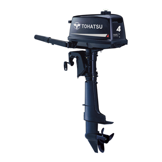
PARTS NAME ENOM01401-0 4C, 5B-D, 5B-S 5B-S Separate Fuel Tank 5B-D Dual Fuel Tank ENOF02102-1 Air Vent Screw Starter Handle Choke Knob Fuel Tank Cap Shift Lever Stop Switch Tilt Handle Throttle Glip Fuel Cock Knob Top Cowl Clamp Screw Fuel Connector Bottom Cowl Clamp Bracket... - Page 15 PARTS NAME ENOM00822-0 Fuel tank ENOF02103-1 Air vent screw Fuel tank cap Fuel connector (Engine side) Primer bulb Fuel connector (Fuel tank side)
-
Page 16: Label Locations
LABEL LOCATIONS ENOM01402-0 Warning label locations 1, 2 4, 5 ENOF02104-2... - Page 17 LABEL LOCATIONS 1, 4. Read owner's manual. 314X72185-0 Warning regarding gasoline (See 3F0X72185-0 page 23). Engine stop switch (See page 34). ENOF00131-B HOT SURFACE. Can cause burns. ENOF00005-S Warning regarding gasoline (See page 23). 3GR-76191-0 HOT SURFACE Can cause burns. Do not touch when operating or ENOF00005-L immediately after stop the engine.
- Page 18 LABEL LOCATIONS ENOM01001-0 Serial number label locations ENOF02105-2 1. Model code (Model name) 2. Serial No. 3. Rated power 4. Dry mass weight 5. Manufacture name 6. Manufacture address 7. Authorised representative 8. Authorised representative address Description of serial number year code Last two digits of alphabet represent production year as below.
-
Page 19: Installation
INSTALLATION Keep the outboard motor in a vertical ENOM00024-B 1. Mounting the outboard position when mounting. motor on boat ENOW00006-0 WARNING Most boats are rated and certified in terms of their maximum allowable horsepower, as shown on the boat’s certification plate. Do not equip your boat with an outboard motor that exceeds this limit. - Page 20 INSTALLATION ENOM00026-0 ENOM00831-0 Transom matching Mounting the outboard motor Be sure that the anti ventilation plate of 1. Set the outboard motor to appropri- the outboard motor is 30–50 mm (1.2–21 ate position. in) below the bottom of hull. 2. Tighten the clamp screws by turning If the above condition cannot be met due their handles.
-
Page 21: Pre-Operating Preparations
ENOM00032-A GASOLINES CONTAINING CAUTION ALCOHOL When operating a TOHATSU engine on gaso- The fuel system components on your line containing alcohol, storage of gasoline in TOHATSU engine will withstand up to 10% the fuel tank for long periods should be ethyl alcohol (here in after referred to as avoided. -
Page 22: Engine Oil Recommendation
PRE-OPERATING PREPARATIONS protective oil films from internal compo- nents. Fuel by Oil Mixing (25:1, 50:1) ENOW00018-0 1.0L (25:1) 25: 1 WARNING 0.48L Fuel leakage can cause fire or explosion, (25: 0.5) (12:0.48) 50: 1 potentially leading to severe injury or loss of 0.24L (12:0.24) life. -
Page 23: Fuel Filling
PRE-OPERATING PREPARATIONS through air vent screw when it is open. Leak- ing gasoline is a dangerous fire hazard. ENOW00028-A WARNING Consult an authorized dealer for details on handling gasoline, if necessary. Gasoline and its vapors are very flammable and can be explosive. When carrying a fuel tank containing gaso- line: Close the fuel tank cap and air vent screw... - Page 24 PRE-OPERATING PREPARATIONS Dispose aged or contaminated gasoline in 1. Air vent screw 2. Fuel tank cap accordance with local regulations. 2. Open the fuel tank cap slowly. ENOW00029-A 3. When using integral tank WARNING Remove top cowl and fill the fuel not When opening fuel tank cap, be sure to fol- to over the full mark.
-
Page 25: Break-In
PRE-OPERATING PREPARATIONS ENOM00033-B 4. Break-In Your new outboard motor and lower unit ENOW00023-1 require break-in for the moving compo- CAUTION nents a ccording to the conditions Operating the outboard motor without described in the following time table. break-in can shorten life of the product. ENOW00024-A If any abnormality is experienced during the break-in:... -
Page 26: Engine Operation
ENGINE OPERATION from engine can cause increase of internal ENOM00042-0 pressure of the tank dangerously. Before starting 1. When using integral tank ENOW00022-B Loosen the air vent screw on the tank CAUTION cap by two turns . Be sure to fill the engine before star ting engine. - Page 27 ENGINE OPERATION 2. Open the fuel tank cap slowly and release internal pressure completely. 3. Set fuel cock lever to which you would like to use. ENOF02113-0 1. Fuel cock 2. Close position (When using separate tank) 3. Open position (When using integral tank) ENOF02112-0 1.
-
Page 28: Starting The Engine
ENGINE OPERATION ENOW00959-0 CAUTION The top cowl must be installed while the engine running except in an emergency. If the top cowl is not installed correctly, water splash can damage the engine. ENOW00036-A CAUTION ENOF00861-A 1. Pull When the engine is started in the test tank, 2. - Page 29 ENGINE OPERATION 2. Set the control lever in the Neutral ENOW00032-B position. CAUTION Do not try to crank after engine has started. This model is provided with start in gear protection. ENON00010-0 Note Start-in-gear protection prevents engine ENOF02116-0 from starting at other than neutral shift. In-gear starting of engine will move the 1.
- Page 30 ENGINE OPERATION ENOM00042-A ENON00501-A Emergency starting Note ENOW00099-A Choke is not necessary when the engine is WARNING warm. When the emergency starter rope is used for ENON00502-0 Note starting engine; Start in gear protection does not work. Be If engine does not start with 4 or 5 times sure to shift is at neutral position.
- Page 31 ENGINE OPERATION 2. Disconnect the rink of the starter 5. Tie a loop in the another end of the lock rod. emergency starter rope and attach socket wrench that is included in the tool kit. ENOW00860-0 CAUTION Be sure to keep the harness away from the rotation parts.
-
Page 32: Warming Up The Engine
ENGINE OPERATION ENOM0004B-0 ENOM00046-A 3. Warming up the engine 4. Forward, reverse, and acceleration ENOW00932-0 CAUTION ENOW00037-0 WARNING Be sure to check that cooling water is com- ing out of the cooling water check por t Before shifting into forward or reverse, make during warm up. - Page 33 ENGINE OPERATION ENOW00861-0 ENOM00890-A Tiller handle type WARNING ENOW00867-0 Do not shift at high boat speed, or control WARNING may be lost, falling down or causing passen- ger(s) to be thrown overboard. Leading to Sudden acceleration and deceleration may serious personal injury. cause passenger(s) to be thrown overboard or falling down.
-
Page 34: Stopping The Engine
ENGINE OPERATION ENOF02115-A1 ENOF02115-B1 1. Throttle grip 1. Throttle grip 2. START position 2. START position 3. Fully closed 3. Fully closed 4. Fully opened 4. Fully opened 2. Put the shift lever in the Neutral posi- ENOM00049-A tion. 5. Stopping the engine Run the engine for 2-3 minutes at idling speed for cooling down if it has ENOW00868-0... -
Page 35: Steering
ENGINE OPERATION Disconnect the fuel connector of the ENOM00920-A engine and the fuel tank. 6. Steering Emergency engine stopping ENOW00870-0 Remove stop switch lock to stop the WARNING engine. Sudden steering may cause passenger(s) to be thrown overboard or falling down. Tiller handle type Right turn Move the tiller handle to the left... - Page 36 ENGINE OPERATION ENOW00044-0 WARNING Excessive trim up or down may lead to unsta- ble boat operation, potentially causing the steering difficulty that leads to accident during cruising. Do not cruise at high speed if improper trim position is suspected. Stop the boat ENOF00052-0 and readjust trim angle before continuing cruise.
-
Page 37: Tilt Up And Down
ENGINE OPERATION 4. Remove the thrust rod as shown pic- ENOW00056-A ture. WARNING When tilting up outboard motor with fuel joint for over a few minutes, be sure to dis- connect fuel hose, or fuel may leak, poten- tially catching fire. ENOW00057-0 CAUTION Do not tilt up outboard motor while engine... -
Page 38: Shallow Water Operation
ENGINE OPERATION ENOM00068-A 9. Shallow water operation ENOW00051-0 WARNING During shallow water operation, be careful not to place your hand between the swivel bracket and the clamp bracket. Be sure to tilt the outboard motor down slowly. ENOW00053-0 CAUTION ENOF00442-0 1. - Page 39 ENGINE OPERATION Manual tilt type Shallow water running position: 1. With the shift lever in Neutral or For- ward, tilt the motor up slowly by about 40° and then lower the tilt lever for setting at the shallow water run- ning position.
-
Page 40: Removing And Carrying The Outboard Motor
REMOVING AND CARRYING THE OUTBOARD MOTOR Fuel leakage is a fire or explosion hazard, ENOM00070-F which can cause serious injury or death. 1. Removing the outboard motor ENOW00065-0 WARNING ENOW00064-A CAUTION Close air vent screw of fuel tank before car- rying or storing outboard motor and fuel Engine may be hot immediately after operat- tank, or fuel may leak, potentially catching... -
Page 41: Trailering
REMOVING AND CARRYING THE OUTBOARD MOTOR ENOF00075-1 ENOW00068-0 WARNING Close air vent screw of fuel tank and fuel cock before carrying or storing outboard motor and fuel tank, or fuel may leak, poten- tially catching fire. ENOF02131-0 ENON00021-C Note ENOW00071-0 CAUTION If the outboard motor must be laid down, be sure drain the fuel from the fuel line... - Page 42 REMOVING AND CARRYING THE OUTBOARD MOTOR When transporting a boat on a trailer with the outboard motor still attached, disconnect the fuel line from the out- board motor beforehand and keep the outboard motor in the normal running position or on a transom saver bar. Tiller handle type To prevent the outboard motor from moving when it is attached on a boat...
-
Page 43: Adjustment
ADJUSTMENT ENOM00073-E EENOM00074-A 1. Steering friction 2. Throttle grip friction Tiller handle type ENOW00074-B WARNING ENOW00074-F WARNING Do not overtighten the throttle adjustment screw or it could result in difficulty of move- Do not over tighten the steering friction ment resulting in the loss of control causing adjustment screw it could result in difficulty an accident and could lead to severe injury. -
Page 44: Inspection And Maintenance
INSPECTION AND MAINTENANCE ENOM00077-0 Care of your outboard motor To keep your outboard motor in the best operating condition, it is very important that you perform daily and periodic maintenance as suggested in the mainte- nance schedules that follow. ENOW00077-0 CAUTION Your personal safety and that of your pas- sengers depends on how well you main-... -
Page 45: Daily Inspection
INSPECTION AND MAINTENANCE ENOM01403-0 1. Daily Inspection Perform the following checks before and ENOW00078-0 after use. WARNING Do not use outboard motor if any abnormal- ity is found during pre-operation check or it could result in severe damage to the motor or severe personal injury. - Page 46 INSPECTION AND MAINTENANCE ENOM00083-0 ENOM00085-E Washing outboard motor Flushing attachment ENOW00922-0 ENOW00081-0 CAUTION WARNING To prevent the engine from starting when Do not start engine without removing pro- you are near the propeller, remove the stop peller, or accidentally turning propeller switch lock.
- Page 47 INSPECTION AND MAINTENANCE ENOM00085-A Flushing by test tank ENOW00081-0 WARNING Do not start engine without removing pro- peller, or accidentally turning propeller could cause personal injury. ENOW00082-0 WARNING Never start or operate the engine indoors or in any space which is not well ventilated. Exhaust gas contains carbon monoxide, a colorless and odorless gas which can be fatal if inhaled for any length of time.
-
Page 48: Periodic Inspection
INSPECTION AND MAINTENANCE ENOM01404-0 2. Periodic Inspection It is important to inspect and maintain your outboard motor regularly. At each interval on the chart below, be sure to perform the indicated servicing. Maintenance intervals should be determined according to the number of hours or num- ber of months, whichever comes first. - Page 49 INSPECTION AND MAINTENANCE ENOM00093-A Fuel filters and fuel tank cleaning ENOW00093-B WARNING Gasoline and its vapors are very flammable and can be explosive. Keep out of reach of children. Avoid repeated or prolonged contact with skin or breathing of vapor. Place fuel filter away from every source of ignition such as sparks or open flames.
- Page 50 INSPECTION AND MAINTENANCE lamation. Do not throw it in the trash, pour it on the ground or down a drain. 1. Tilt down the outboard motor. 2. Remove the oil plugs (lower and upper), and completely drain the gear oil into a pan. ENOF01226-1 1.
- Page 51 INSPECTION AND MAINTENANCE ENOW00928-0 CAUTION Wipe off gear oil well immediately if spilled and dispose of it in accordance with local fire prevention and environment protection regulations. ENON00032-0 Note If water in the oil, giving it a milky colored appearance. Contact your dealer. ENOM00086-A ENOF01515-0 Propeller replacement...
- Page 52 INSPECTION AND MAINTENANCE 1. Put a piece of wood block between 6. Tighten the propeller nut to specified propeller blade and anti-ventilation torque, and align one of grooves to plate to hold propeller. propeller shaft hole. Propeller nut torque: 12 Nm (9 ft lb, 1.2 kgf 7.
- Page 53 INSPECTION AND MAINTENANCE to specification. turn past finger-tight. Have the spark plug adjusted to the correct torque as soon as possible with a torque-wrench. 1. Stop the engine. 2. Remove the top cowl. 3. Remove the spark plug caps. 4. Remove the spark plugs by turning it counter-clockwise, using a 13/16"...
- Page 54 INSPECTION AND MAINTENANCE ENOM00088-A Anode replacement A sacrificial anode protects the outboard motor from electrolytic corrosion. Anode is located on the gear case, cylinder etc.. When the anode is eroded more than 1/3 of original size, replace it. ENON00029-0 Notes Never grease or paint the anode.
- Page 55 INSPECTION AND MAINTENANCE ENOM00960-0 Grease point Apply water proof grease to the parts shown below. ENOF02139-0...
-
Page 56: Off-Season Storage
INSPECTION AND MAINTENANCE 3. Drain all fuel from the fuel hoses and ENOM00100-A 3. Off-season storage carburetor (See page 57), and clean these parts. ENOW00934-0 Keep in mind that if gasoline is kept in the carburetor for a long time, gum WARNING and varnish will develop, causing the Be sure to disconnect fuel connector... - Page 57 INSPECTION AND MAINTENANCE 2. Follow the instructions on the label ENOW00066-1 when adding the fuel stabilizer addi- CAUTION tive. Do not carry or store outboard motor in any 3. After adding the additive, let the out- of positions described below. board motor run in the water for 10 Otherwise, engine's exterior parts may be minutes to make sure any old fuel in...
-
Page 58: Pre-Season Check
INSPECTION AND MAINTENANCE 2. Remove the top cowl. 1. Check that the shift and throttle function properly. (Be sure to turn the 3. Place an approved rag under the propeller shaft when checking the drain screw and use a funnel to avoid shift function or else the shift linkage spilling fuel. -
Page 59: Cold Weather Precautions
INSPECTION AND MAINTENANCE 2. Remove the spark plugs, and com- pletely drain the water from the engine by pulling recoil starter several times. 3. Inject a sufficient amount of engine oil through the spark plug holes. Pull the recoil starter rope several times to circulate the oil throughout the outboard motor. -
Page 60: Troubleshooting
TROUBLESHOOTING ENOM01406-0 If you encounter a problem, consult the check list below to determine the cause and to take the proper action. An authorized dealer will always be happy to provide any assistance and information. Possible cause Empty fuel tank Incorrect connection of fuel system Air entering fuel line Deformed or damaged fuel hose... - Page 61 TROUBLESHOOTING Possible cause Incorrect adjustment of throttle link Insufficient cooling water flow, clogged or defective pump Faulty thermostat Cavitation or ventilation Incorrect propeller selection Damaged or bent propeller Improper thrust rod position Unbalanced load on boat Transom too high or too low...
-
Page 62: Tool Kit And Spare Parts
TOOL KIT AND SPARE PARTS ENOM01407-0 Name Quantity Remark Tool bag Pliers Socket wrench 10 × 13 mm Service tools Socket wrench 21 mm Socket wrench handle Screwdriver (Phillips-type Adapter-type and flat head) Emergency starter rope 1000 mm Spare stop switch lock Spare parts Spark plug NGK: BPR 7HS-10... -
Page 63: Propeller Table
PROPELLER TABLE ENOM01408-0 Use a genuine propeller. A propeller must be selected so that the engine min (rpm) measured at wide open throttle while cruising is within the recommended range. 4: 4500–5500 min (rpm) 5: 4500–5500 min (rpm) Propeller Size (Diameter × pitch) Propeller Mark inch... - Page 68 O W N E R’ S M A N U A L M 4C M 5B 5-4, Azusawa 3-Chome, Itabashi-Ku Tokyo 174-0051, Japan Tel: +81-3-3966-3117 Fax: +81-3-3966-0090 www.tohatsu.com...
Need help?
Do you have a question about the M 4C and is the answer not in the manual?
Questions and answers