Table of Contents
Advertisement
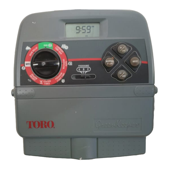
Automatic Sprinkler System Controller
MANUAL
START
PROGRAMS
A
B C
R
(For Indoor Use Only)
User's Guide
GreenKeeper 212 Features:
• Easily Expandable Up To 12 Stations
With 2-Station Plug-In Modules
• 3 Watering Programs With:
ON
- Calendar, Interval and Odd/ Even Days
NEXT
- 1 Min. to 4 Hrs. Zone Run Time
- 4 Start Times Per Program
OFF
• Battery Back-Up
• Automatic Pump Start
• Seasonal Run Time Adjust
• Rain Delay
• Rain Sensor Ready
• Remote Control Ready
• Snap-In Wire Connectors
Advertisement
Table of Contents

Related Manuals for Toro Green Keeper 212


Summary of Contents for Toro Green Keeper 212
- Page 1 User’s Guide Automatic Sprinkler System Controller GreenKeeper 212 Features: • Easily Expandable Up To 12 Stations With 2-Station Plug-In Modules • 3 Watering Programs With: - Calendar, Interval and Odd/ Even Days MANUAL NEXT START - 1 Min. to 4 Hrs. Zone Run Time PROGRAMS - 4 Start Times Per Program •...
-
Page 3: Table Of Contents
■ Watering Program Details ......8-9 Connecting The Transformer......24 ■ ■ Planning Your Watering Schedule....10 Connecting A Toro Rain Switch.......25 ■ ■ Filling Out The Watering Schedule Form ...10-11 ■ Cont rolle r Ope ra t ion Watering Schedule Form ......12 ❚... - Page 4 GreenKeeper 212 Introduction and Set Up Cont rolle r Com pone nt s BATTERY...
-
Page 5: Greenkeeper 212 Components
Gre e nK e e pe r 2 1 2 Com pone nt s 2 - Control Buttons The following are brief descriptions of the controller com- ponents and display elements. Each of these items will button – Increases the time display, scrolls for- be explained in further detail within the appropriate pro- ward through the program information and selects gramming, operating and installation sections of this... - Page 6 11 - Sensor Connection Terminals – Snap-in connec- Cont rolle r Com pone nt s tors for connection of an (optional) Toro Rain Switch. 3 - Control Dial Positions (continued) 12 - Common Connection Terminal – Snap-in wire – Enables the run time of all SEASON ADJ U ST connector for the valve common wire.
- Page 7 Cont rolle r Com pone nt s BATTERY...
-
Page 8: Sprinkler System Basics
Sprinkler System Basics The three main components of every automatic sprinkler system are the controller, station control valves and sprinklers. Valve 1 Controller The controller is the brain of the system, telling the control valves when and how long to supply water to the sprin- klers. -
Page 9: Watering Program Basics
Watering Program Basics Watering Program Diagram A watering program requires three basic instructions to operate automatically: Program • What days to water –called watering days Starts - 5:00 • When to water – called a program start time Station 1 •... -
Page 10: Watering Program Details
you can choose which day of the week will be the first day Watering Program Details of the Interval. The number of days in the Interval deter- mines the available start days. For example, if you have This section covers in detail each of the three parts of a selected a 3-day Interval and today is Sunday, you may watering program –... - Page 11 Se le c t ing Progra m St a rt T im e s Se t t ing T he St a t ion Run T im e A program start time is the time of day you select to A station run time is the length of time the station (con- begin an automatic program watering cycle.
-
Page 12: Planning Your Watering Schedule
Filling Out The Watering Schedule Form Planning Your Watering Schedule When filling out this form, use a pencil so changes can be It is always helpful to plan your watering schedule on easily made. Carefully remove the page from the booklet paper before beginning the programming steps. - Page 13 (Example)
-
Page 14: Watering Schedule Form
Watering Schedule Form PROGRAM A PROGRAM B PROGRAM C SU MO TU WE TH FR SA SU MO TU WE TH FR SA SU MO TU WE TH FR SA CALENDAR WATERING DAY SCHEDULE INTERVAL ODD/EVEN EVEN EVEN EVEN ZONE LOCATION ZONE RUN TIME ZONE RUN TIME... -
Page 15: Programming Before Installation
Programming Before Installation The GreenKeeper 212 utilizes a 9-volt battery to retain its 2. The display will begin flashing 12:00 . Press the watering program information in the event of a main power button to stop the display from flashing. The interruption. -
Page 16: Selecting Optional Features
Selecting Optional Features About The GreenKeeper 212 Memory 24-Hour Clock Mode The GreenKeeper 212 has a permanent watering sched- ule within its memory to assist you in two ways. First, it The GreenKeeper 212 is Figure 3 will restore watering operation in case your watering pro- set to display time in the gram is lost due to a power interruption lasting longer 12-hour clock mode. -
Page 17: Resetting The Controller Memory
Resetting The Controller Memory The GreenKeeper 212 program memory can be reset to Figure 4 the permanent program values or cleared completely at any time without removing power. Resetting the permanent program erases all user input and replaces it with the permanent program values. Clearing the program memory sets all program values to Off (i.e., no active days, program start times or station run times). -
Page 18: Programming The Controller
Example 1 Programming The Controller Setting The Current Time and Day or Date Note: To select the 24-hour clock mode, see page 14. Turn the control dial to the CU RREN T T I M E position (the hour digits will begin flashing). To adjust the display, press the +/ button to scroll the digits forward or the –/... -
Page 19: Setting The Watering Day Schedule
Setting The Watering Day Schedule For each program, you can select Calendar, Interval Odd, Even or Off. To set a Calendar schedule, continue PGM A here. To set an Interval schedule see page 18. To set an SU MO TU WE TH FR SA Odd or Even schedule see page 19. -
Page 20: Setting An Interval Schedule
Setting An Interval Schedule Turn the control dial to the WAT ERI N G DAY S position. PGM A Check the switch setting. If necessary, PROGRAM S reposition the switch to select the desired program. The current watering schedule will be displayed. If Int (Interval) is not displayed, press the +/ –/ button as needed to select Int. -
Page 21: Setting An Odd Or Even Schedule
Setting An Odd or Even Schedule Turning Off A Program Note:The Odd/Even Selector Jumper must be removed Note: Turning off a program does not alter or erase a this type of watering schedule. See page 14 for details. preset watering day schedule. Selecting Off simply places the program on hold until one of the watering day Turn the control dial to the WAT ERI N G DAY S... -
Page 22: Setting Program Start Times
Setting Program Start Times Turn the control dial to the PROGRAM ST ART T I M E position. PGM A Check the switch setting. If necessary, PROGRAM S reposition the switch to select the desired program. 3 5 7 Program start time number 1 will begin flashing. The current program start time or OFF will be displayed for start time number 1. -
Page 23: Setting Station Run Times
Setting Station Run Times Turn the control dial to the ST AT I ON T I M ES position. PGM A Check the switch setting. If necessary, PROGRAM S 1 2 3 4 5 6 reposition the switch to select the desired program. Station number 1 will be flashing and its current run time or OFF will be shown. -
Page 24: Installation
Installation Note: The GreenKeeper 212 controller is not weather resistant and must be installed indoors or in a pro- tected area. For outdoor installation, a weather-resistant outdoor cabi- net is available. Order model number GK212-CAB-01 for domestic controllers or GK212-CAB-02 for export controllers. -
Page 25: Connecting The Valves
Connecting The Valves 1. Route the valve control wires between the valves and the controller. Note: Using 18 AWG (0.75mm ) multi-wire sprinkler BATTERY valve connection cable is recommended. This cable is insulated for direct burial and is color-coded to sim- plify installation. -
Page 26: Connecting A Pump Start Relay
Connecting A Pump Start Relay Connecting The Transformer (Optional) Note: For model GK212-26-04, contact your Toro dis- tributor for the recommended transformer. CAUTION: To prevent controller damage, ensure the relay current draw does not exceed CAUTION: Do not plug the transformer into an 0.35 Amps. -
Page 27: Connecting A Toro Rain Switch
Connecting A Toro Rain Sw itch (Optional) The Toro Rain Switch is a remote rain sensor which can Toro Rain Switch be connected directly to your GreenKeeper 212 to auto- matically interrupt watering during rain. A sensor bypass switch is provided which enables the Rain Switch operation to be turned On and Off. -
Page 28: Controller Operation
The Automatic mode is selected when the control dial is Controller Operation in the position. While in the automatic mode, the RU N display will show two types of information: status and operation. The GreenKeeper 212 controller has three modes of This illustration shows the operation: Automatic, Manual and Off. -
Page 29: Starting Programs Or Stations Manually
Manual Operation Manual operation enables the automatic watering pro- Flashing grams or selected stations assigned to the program to be PGM A B Flashing started manually. During operation, temporary changes 1 2 3 4 5 6 can be made to increase or decrease the station run time, step through the station sequence and pause or stop watering using the “Watering Control Features”... -
Page 30: Watering Control Features
To Cancel Watering Watering Control Features Press the +/ and –/ buttons at the same time - The following watering control features enable you to fur- two times. ther control the watering program during operation. • All watering operations will be canceled and the con- All watering control features apply to watering programs troller will return to the automatic mode. -
Page 31: Turning Off The Greenkeeper 212
Turning Off The GreenKeeper 212 Flashing When the control dial is turned to the position, the controller immediately shuts off any watering operation currently in progress. Leaving the control dial in the position will prevent all automatic and manual watering operations. The controller will continue to track the current time and day of the week. -
Page 32: Using The Season Adjust Feature
Using The Season Adjust Feature Changes in season and temperature generally require a change in station run time to maintain a healthy land- scape and conserve water. The season adjust feature enables you to change the run time of all zones assigned to a program, simultaneously up or down, in 10% incre- ments –... -
Page 33: Service And Specifications
Adding A Station Module Service and Specifications 1. Turn the control dial to the position. 2. Remove the lower front cover from the controller housing by sliding it downward. Replacing The Fuse A 0.75 Amp fuse protects the controller from damage due to power surges and excessive current draw through the Station Modules. -
Page 34: Troubleshooting
If you are having a problem with the controller, check the following symptoms, possible causes and remedies. If the problem cannot be resolved or you would like assistance with any Toro irrigation product, call our toll-free Toro Help Line, 1-800-664-4740 Monday through Friday, 7:30 –... -
Page 35: Specifications
• Output: 24 V a.c. 50/60 Hz; 18VA ucts and products sold outside of the United States, have a one-year limited warranty from date of installation. Toro is not liable for failure of products not Power Specifications, Export Model: manufactured by Toro, even though such products may be sold or used in Plug-In Transformer, TUV Approved conjunction with Toro products. -
Page 36: Electromagnetic Compatibility
Printing Office, Washington, DC 20402. Stock the interference by one or more of the following mea- No. 004-000-00345-4. sures: International: This is a CSPR 22 Class B product. 1999 The Toro Company, Irrigation Division Form Number 373-0063 Rev. A ©...
Need help?
Do you have a question about the Green Keeper 212 and is the answer not in the manual?
Questions and answers
My Green Keeper Torro controller F symbol -Water OFF is permanently displayed. so watering system is not working, ive tried resetting, disconnecting supply and battery and reprogramming everything but still no luck