Advertisement
Available languages
Available languages
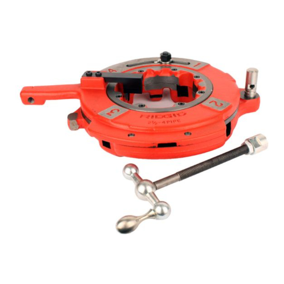
725 Cut-Grooving Die Head Instruction Sheet
725 Cut-Grooving Die Head Instructions
WARNING
serious personal injury.
• Do not wear gloves, loose clothing, or jewelry when operat-
ing machine. Keep sleeves and jackets buttoned. Clothing can
be caught by the pipe or tool resulting in entanglement.
• Keep hands away from rotating pipe and parts. Allow the
machine to come to a complete stop before touching the pipe or
tool. This reduces the risk of en tanglement, crushing or striking
injuries.
If you have any question concerning this RIDGID
– Contact your local RIDGID distributor.
– Visit www.RIDGID.com to find your local RIDGID contact point.
– Contact Ridge Tool Technical Service Department at rtctechser-
vices@emerson.com, or in the U.S. and Canada call (800) 519-
3456.
Description
The RIDGID
®
725 Cut Grooving Die Head is used to cut AWWA C606
(15) specification grooves into 2
(not for use on stainless steel). The 725 Cut Grooving Die Head is for
use with the RIDGID 1224 Threading Machine.
Lever
Washer
Index Line
Feed Screw
Cutting
Die
Jam Nut
Adjusting Nut
Cam Locking
Plate
Die Head
Stop
Figure 1 – 725 Cut-Grooving Die Head
Inspection/Maintenance
Clean the die head to aid inspection and improve control. Inspect the
die head before each use for proper assembly, wear, damage or other
issues that could affect safe use.
Inspect the cutting edges of the dies. Dull or damaged cutting tools
increase required force and increase the risk of injury. If any problems
are found, do not use until corrected.
Set Up and Operation
Make sure all equipment is inspected and set up per its instructions.
Always cut a test groove to confirm proper groove size after chang -
ing/adjusting the dies. See"Inspecting the Groove" section.
Inserting/Changing the Dies
The die head requires separate set of dies for (2
(4") pipe size ranges. A cut grooving die set consists of three guide dies
and one cutting die.
1. Place the die head with
numbers facing up.
2. Loosen the cam bolt nut
approximately six full turns.
3. Lift tongue of lever wash er
out of the slot and open
the die head by moving
the cam bolt in the direc-
tion of the larg est size pipe
on cam plate (Figure 2).
4. Remove dies from the die
head.
Printed 12/15
The Emerson logo and RIDGID logo are registered trademarks of Emerson Electric Co. or RIDGID, Inc. in the U.S. and other countries.
EC41759
Read these instructions and
the warnings and instruc tions
for all equipment and material
be ing used before operating
this tool to reduce the risk of
®
product:
1
/
" - 4" IPS dimension metallic pipe
2
Cam Bolt Nut
Guide Die
1
/
" through 3
1
/
2
2
Groove
Guide Die
Cutting Die
Figure 2 – Inserting Dies
All other trademarks belong to their respective holders.
5. Insert groove cut ting die (marked "4") into the number 4 die head
slot. Guide dies are not marked and are used in the 1, 2 and 3
die head slots. Insert numbered edge/ notch facing up until the
indicator line on die is flush with the edge of the die head
(Figure 2).
6. Move cam bolt to align desired size mark with index line. Adjust die
insertion as needed to allow movement. Wash er tongue should
be in slot to left (Figure 1). Tighten the cam bolt nut.
Adjusting Pipe Size
Loosen the cam bolt nut and rotate cam locking plate to desired size
setting. Tighten the nut.
Cutting A Groove
Refer to the 1224 Threading Machine Operator's Manual for informa-
tion on machine set-up and operation. Cut grooving should be done
at 36 rpm.
1. On 1224, pull sine bar out away from the chuck and rotate the
latch down to hook it to the carriage.
2. Lower the die head into operating position.
3. Turn feed screw to retract dies and prevent die contact with pipe.
4. Move the REV/OFF/FOR switch to FOR position.
5. Turn the carriage handwheel to bring the die head stop against
end of pipe. Hold the handwheel in position to prevent the stop
from moving away from the pipe end. This sets the gasket seat
length of the groove.
6. Depress foot switch. Confirm oil flow through the die head.
7 . While holding stop against end of pipe, slowly turn the feed
screw assembly to feed groove die into pipe and cut groove.
Keep feedscrew end in contact with carriage.
8. Continue to advance feed screw until proper groove diameter is
reached. Allow pipe to make 3 to 4 revolutions to clean up any
extra material left in groove.
9. Set the adjustment nut against the cam locking plate and retain
with the jam nut for more repeatable groove size.
10. Once cutting operation is complete and while pipe is still rotating,
turn feed screw to retract grooving die clear of the pipe diameter.
11. Remove foot from the foot switch.
12. Move the FOR/OFF/REV switch to the OFF position.
13. Turn carriage handwheel to move the die head past end of the
pipe. Raise the die head into the position up away from the oper-
ator.
14. Remove the pipe from machine and inspect the groove.
Feed Screw
Jam Nut
") and
Die Head Stop
Die Head Stop
Figure 3 – Grooving the Pipe
Inspecting the Groove
1. Measure the groove diameter. Compare the dimension to the
requirement in Table I or as specified by the groove fitting manu-
facturer. Adjust adjustment nut and jam nut as needed. One
rotation of the adjustment nut changes groove diameter approx-
imately 0.02".
2. Measure gasket seat width. Compare the di men sion to the require-
ment in Table I or as specified by the groove fitting manufacturer.
3. Visually inspect the groove for form and other items required by the
fitting manufacturer. If any issues are found, the groove cannot be
used. Out of spe ci fi cation grooves could cause joint failure.
©2015, RIDGID, Inc.
999-998-256.10
REV. A
Advertisement
Table of Contents

Related Manuals for RIDGID 725


Summary of Contents for RIDGID 725
- Page 1 ©2015, RIDGID, Inc. Printed 12/15 999-998-256.10 The Emerson logo and RIDGID logo are registered trademarks of Emerson Electric Co. or RIDGID, Inc. in the U.S. and other countries. EC41759 REV. A All other trademarks belong to their respective holders.
- Page 2 Figure 1 – Tête de filière de rainurage n° 725 Reportez-vous au manuel de la fileteuse 1224 pour les modalités d’e La tête de filière de rainurage n° 725 est prévue pour la coupe de rain- préparation et d’utilisation de la machine. La coupe des rainures se fait ures type AWWA C606 (15) dans les tuyaux métalliques (à...
- Page 3 AWWA C606 (15) en tubos metálicos IPS de diámetro 2 " a 4" (no debe usarse con acero inoxidable). El cabezal ranuradoras 725 de terrajas ranuradoras 725 se usa con la roscadora 1224 de RIDGID. ¡ ADVERTENCIA! Tuerca de ajuste de la Arandela...
- Page 4 Quick-Opening Die Head Instruction Sheet Puesta en marcha y operación 6. Oprima el interruptor de pie. Confirme que el aceite fluya por el cabezal de terrajas. Asegure que todos los equipos se hayan inspeccionado e instalado de acuerdo con sus instrucciones. 7 .
Need help?
Do you have a question about the 725 and is the answer not in the manual?
Questions and answers