Table of Contents
Advertisement
Quick Links
West House, West Avenue, Wigston, Leicester LE18 2FB, United Kingdom, Tel: +44 (0)116 200 1757, Fax: +44 (0)116 284 9243
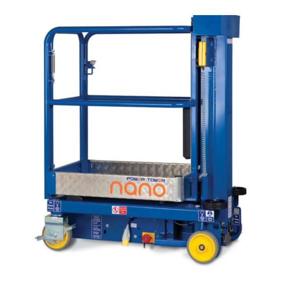
Working Dimensions
Maximum working height: 4.50 m
Maximum platform height: 2.50 m
Platform dimensions: 1.00 m x 0.73 m
Working footprint: 1.19 m x 0.75 m
Safe working load: 200 kg (1 person plus tools)
Maximum manual force: 200 N
Max. gradient for operation: 0°
Max. wind force: Indoor use 0 mph
Manual push force on level ground: 9 kg
Maximum total weight inc payload: 485 kg
Maximum castor point load: 180 kgs (1.77 kN)
Max. wheel force: 1.75 kN
Closed Dimensions
Length: 1.195 m
Width: 0.750 m
Height: 1.560 m
Weight: 285 kg
Power Source
Standard 12v DC Electric Motor
Or 240V AC Electric Motor 13A Supply
Or 110V AC Electric Motor 16A Supply
Battery Charger Specification
Input Voltage:
If single voltage: 90-135V AC (UK)
180-265V AC (non-UK)
If dual voltage: 90-265V AC
Frequency: 45-65 Hz
Output: 12V DC, 7A
Power sound level: Less than 70dB
Power Towers Ltd,
sales@powertowers.com | www.powertowers.com
Advertisement
Table of Contents

Related Manuals for Power Towers nano


Summary of Contents for Power Towers nano
- Page 1 If dual voltage: 90-265V AC Frequency: 45-65 Hz Output: 12V DC, 7A Power sound level: Less than 70dB Power Towers Ltd, West House, West Avenue, Wigston, Leicester LE18 2FB, United Kingdom, Tel: +44 (0)116 200 1757, Fax: +44 (0)116 284 9243 sales@powertowers.com | www.powertowers.com...
-
Page 2: Table Of Contents
Content Page 3 – 4 Battery Maintenance Battery Charging Fault Checking for Oil Leaks How to Change the Oil in the Hydraulic System Adjusting the Wear Screws (Mast Section) Castor and Wheel Maintenance Replacement of Castor Wheel Gate Latch Adjustment 12 –... -
Page 3: Battery Maintenance
Battery Maintenance Please ensure, the unit is isolated and you use the correct PPE as indicated. Check the electrolyte level in each of the battery cells. The electrolyte should be covering the plates by one to two millimetres Check the connections and make sure the battery is clean Using a hydrometer, check the specific gravity of each cell in the battery. - Page 4 Use a voltmeter to check the voltage. The reading should be approximately 13 volts.
-
Page 5: Battery Charging Fault
Battery Charging Fault Please ensure, the unit is isolated and you use the correct PPE as indicated. Check the battery charger lights when first switched on (Display Green LED On, Amber LED blinking fast is bulk load, blinking slow is absorption, on float, off storage.) If the both charger lights flash slowly, check the fuse, battery connections and... -
Page 6: Checking For Oil Leaks
Checking for Oil Leaks Please ensure, the unit is isolated and you use the correct PPE as indicated. Remove covers spine end cap and the chassis top cover and check the pipe end connections at the base of the lift cylinder ensure the union is torque to 40Nm and also check the connections on... -
Page 7: How To Change The Oil In The Hydraulic System
How to Change the Oil in the Hydraulic System Please ensure, the unit is isolated and you use the correct PPE as indicated. Use a syringe to empty the hydraulic reservoir. Refill with 4.5 litres of grade 32 mineral oil. Elevate the machine from the Pendant controls to ensure the platform reaches full travel. -
Page 8: Adjusting The Wear Screws (Mast Section)
Adjusting the Wear Screws (Mast Section) Please ensure, the unit is isolated and you use the correct PPE as indicated. Raise the mast sections using the lift control to gain comfortable access to the wear screws. Align the outer section to the inner section so that the gap between the inner section and the outer section is equidistant from side to side. -
Page 9: Castor And Wheel Maintenance
Castor and Wheel Maintenance Please ensure, the unit is isolated and you use the correct PPE as indicated. Ensure the Castor bolt is torque to 55Nm, If the castor bolts are to be found to be worn then replace with PT-M-170. Again ensure this is tightened and torqued to 55Nm. -
Page 10: Replacement Of Castor Wheel
Replacement of Castor Wheel Please ensure, the unit is isolated and you use the correct PPE as indicated. Raise the machine from the ground with a suitable hoist or block the front of the machine so the castor wheels are clear of the ground by approximately 50 millimetres. -
Page 11: Gate Latch Adjustment
Gate Latch Adjustment Please ensure, the unit is isolated and you use the correct PPE as indicated. Offer the gate to the hinges and pass the long pivot bolt downward through the top hinge bracket. When feeding downward, slide the bolt though the spring until just before passing through the lower hinge bracket. -
Page 12: Removing Or Replacing The Hydraulic Pipe
Removing or Replacing the Hydraulic Pipe Please ensure, the unit is isolated and you use the correct PPE as indicated. Lower the platform to the transport position, raise the cage and lock the gas strut. Open the manual emergency lowering valve and allow the oil to drain to the tank for a minute or two. - Page 13 The new pipe is refitted in the reverse sequence. Ensure to connect both ends of the pipe loosely to ensure correct alignment and then tighten the cylinder connection first, taking care not to twist the pipe. It may be necessary to slacken the two power pack mounting screws located under the middle of the power When replacing the power pack mounting screws...
-
Page 14: Remove Or Replace The Emergency Lowering Valve
Remove or Replace the Emergency Lowering Valve Please ensure, the unit is isolated and you use the correct PPE as indicated. Fully lower the platform and open the emergency-lowering valve for a minute or two, to fully drain the oil. To open the emergency lowering valve push the milled knobs in and slightly turn anticlockwise. - Page 15 Move the power pack sideways to gain full access to the lowering valve. Remove the knurled knob and solenoid, and then the valve cartridge Refit the new or repaired valve cartridge and reassemble using the reverse sequence. Set the knurled knob in the normally closed locked position to close the emergency lowering valve push in and slightly turn clockwise, check that the...
-
Page 16: Removing Or Replacing The Lift Cylinder
Removing or Replacing the Lift Cylinder Please ensure, the unit is isolated and you use the correct PPE as indicated. Open the emergency lowering valve and ensure the platform is fully lowered. Allow the oil to drain for a minute or two. - Page 17 Undo the four bolts situated around the mast cap and remove. Remove the Spine End Cap. Place suitable oil soak rags on the floor around the base of the machine at the rear, Disconnect the hydraulic pipe from the cylinder, around 0.25 litres of oil may be lost.
- Page 18 With a sling or hoist lift the cylinder clear of the machine. Reverse the procedure to refit the cylinder. When reassembling the mast cap please ensure to apply a small amount of Loctite 648 to the locking bolts and torque to...
-
Page 19: Removal And Assembly Of The Telescopic Mast
Removal and Assembly of the Telescopic Mast Please ensure, the unit is isolated and you use the correct PPE as indicated. Fully lower the platform and open the emergency-lowering valve for a minute or two, to fully drain the oil. To open the emergency lowering valve push the milled knobs in and slightly turn anticlockwise. - Page 20 Remove the tool tray on top of the mast. Remove the countersunk screw in the centre of the mast cap. Undo the four bolts surrounding the mast cap and remove. With the hoist, raise the mast outer section a short distance to a convenient position and remove the roller and wear screws.
Need help?
Do you have a question about the nano and is the answer not in the manual?
Questions and answers