Table of Contents
Advertisement
Advertisement
Table of Contents

Related Manuals for Power Towers 830p


Summary of Contents for Power Towers 830p
- Page 1 Operating and Maintenance Manual www.powertowers.com...
-
Page 2: Table Of Contents
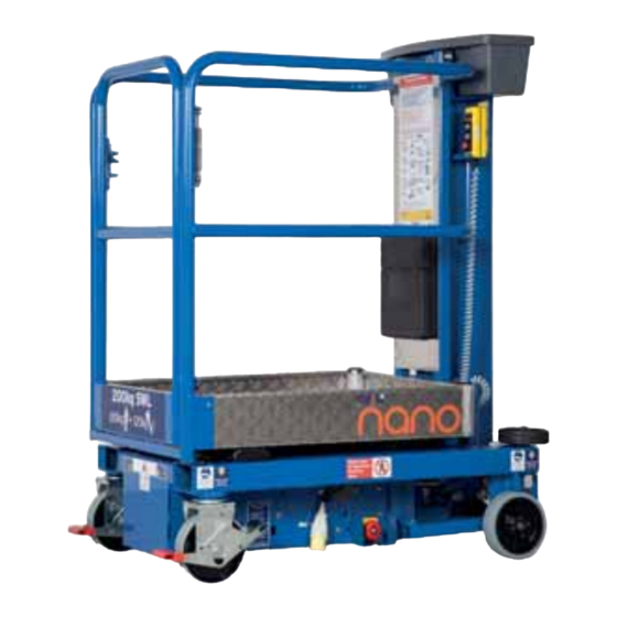
CONTENTS CONTENTS INTRODUCTION The Nano / 830P (referred to as “the machine” in this manual) is designed Introduction to be a simple, quick and safe powered alternative to a portable scaffold tower, podium or a step ladder, for internal construction site Operating Specifications and maintenance applications. -
Page 3: Operating Specifications
OPERATING SPECIFICATIONS Working Dimensions Maximum working height: 4.50 m Maximum platform height: 2.50 m Platform dimensions: 1.00 m x 0.73 m Working footprint: 1.195 m x 0.75 m Safe working load: 200 kg (1 person plus tools) Maximum manual force: 200 N Max. -
Page 4: Do's And Don'ts
21. Never attach loads such as boards or pipes outside the guardrails unless authorised to do so by the manufacturer. Never carry materials directly on the platform guardrails unless approved by Power Towers Ltd. 22. Never use a malfunctioning machine. -
Page 5: Primary Components
PRIMARY COMPONENTS PRIMARY COMPONENT LOCATIONS Entrance Control Gate Latch Auto-Lok Emergency Swivel Emergency Spirit Braked Wheel Castor Level Lowering Valve Stop/Battery Isolator... -
Page 6: Operating Procedures (Incl. Emergency Operation)
OPERATING PROCEDURES Do not operate until inspection and functional checks have been performed as specified below: OPERATING PROCEDURES It is the owners and/or the users responsibility to ensure that the machine is maintained and operated in accordance with the operation and maintenance procedures contained within this manual. - Page 7 OPERATING PROCEDURES PRE-OPERATION CHECKS 1. Ensure there are no obvious signs of mechanical damage to the handrails, platform, lifting structure or chassis. 2. Check platform access gate closes when released and that the latch engages correctly. 3. Check castors and wheels rotate freely and are undamaged. 4.
- Page 8 OPERATING PROCEDURES EMERGENCY LOWERING OPERATION Never attempt to recover the machine/operator if there is any possibility the machine is contacting any live wiring/cabling and is therefore potentially ‘live’ . The Emergency Lowering Procedure is for lowering the platform from height in case of platform control failure or operator incapacity and for no other purpose.
- Page 9 OPERATING PROCEDURES Note: The charger is fitted with a 15A automotive spade fuse (blue). If the BATTERY CHARGING (110V IP20 CHARGER) fuse has failed, the indicator lights will still operate. The fuse may have failed if the battery is heavily discharged and the motor is run when the Check the battery fluid levels and charge in a well ventilated area, only charger is switched on.
- Page 10 OPERATING PROCEDURES Note: The charger is fitted with a 10A automotive spade fuse (red). If the BATTERY CHARGING (110V IP65 CHARGER) fuse has failed, the indicator lights will still operate. The fuse may have failed if the battery is heavily discharged and the motor is run when the Check the battery fluid levels and charge in a well ventilated area, only charger is switched on.
- Page 11 OPERATING PROCEDURES BATTERY CHARGING (230V IP65 CHARGER) Check the battery fluid levels and charge in a well ventilated area, only if Lead Acid batteries are fitted (not required for maintenance free AGM batteries). The battery charger is located under the checkerplate cover (Pic The charging lead is fitted with a black 230V plug and is located on the exterior of the machine base...
-
Page 12: Maintenance Procedures (Incl. Castor Safety And Maintenance)
MAINTENANCE PROCEDURES Please note that whilst the machine is extremely simple to Check all functions operate correctly including movement alarm and emergency stops. maintain, all work must be carried out by a competent person. Ensure mast surfaces are clean and not greased. When removing checkerplate cover for maintenance purposes, first switch off by depressing the emergency stop/battery isolator button located at the base of the machine. - Page 13 If the pins are found to have corrosion they must be replaced. In this case condition of the wheel bearings. On a flat smooth surface the machine please refer to Power Towers technical department for assistance. should move with a force of 9 – 10 kg at the mid guard rail height. The maximum allowance is 20 kg.
- Page 14 Power Towers Limited strongly recommends replacing any castor fixing bolt. THE CASTOR AND FIXING BOLT MUST BE REPLACED.
- Page 15 CASTOR SAFETY & MAINTENANCE It may be thought feasible to repair the castor in a number of these Important. instances, but serious structural damage will have occurred to the head bearing and castor assembly as well as possibly damage to the main These instructions apply to all machines FROM mounting bolt.
-
Page 16: Maintenance Procedures
MAINTENANCE PROCEDURES MAST MAINTENANCE Essentially the mast is maintenance free. The mast sections run on In practice, it is far more likely that the screws may wear so an maintenance free rollers, and on the outer mast surface where the excessive gap between the mast section and the wear screw roller runs, a brush is fitted to keep the mast surface clean, preventing develops. -
Page 17: Maintenance Procedures
MAINTENANCE PROCEDURES MAINTENANCE FREQUENCY The machine must have a thorough (LOLER) examination by a competent person at six monthly intervals. MAINTENANCE FREQUENCY TABLE Item Daily Monthly 6 Months 12 Months Batteries/Connections Battery Specific Gravity Oil Level Visual Inspection Spirit Level Wheels &... -
Page 18: Storage
STORAGE STORAGE If the machine is to be taken out of operation for a period longer than one month, the following precautions should be taken. Ideally, the battery charger should be switched on. The charger has an inbuilt maintenance mode, and will maintain the battery in good condition indefinitely. -
Page 19: Warranty Terms
WARRANTY TERMS WARRANTY IMPORTANT Your Nano / 830P (The Machine) is covered by a parts and Warranty may, at the sole discretion of the Manufacturer, be voided if components warranty as stated in the purchase terms and conditions the scheduled service/inspections are not carried out in accordance (excluding battery and battery charger). -
Page 20: Key Spare Parts
KEY SPARE PARTS ELECTRICAL PARTS Part No. Control box c/w Cable PTN-E-201 Emergency Stop/Battery Isolator PTN-E-200 Battery Isolator Plastic Button PTN-E-206 Battery Charger (110V IP20) PT-E-001 Battery Charger (110V IP65) PT-E-001-2 Battery charger (230V IP65) PT-E-001E 12V 105A Lead Acid Battery PT-E-002 AGM Battery PT-E-002AGM... - Page 21 Cover Securing Knob PT-M-107 Tool Tray PTN-M-303 Buffer Wheel PTN-M-302 Decal Set 1 PTN-M-322 Decal Set 2 (Nano) PTN-M-310 Decal Set 2 (830P) PTN-M-310-2 Keys (pair) PTN-M-341 Gas Strut PTN-M-340 M Checkerplate Cover PTN-M-320 CASTOR CHANGES: (PIC B) BEFORE SERIAL NO. 26953115C (PIC C) FROM SERIAL NO.
-
Page 22: Electric Circuit Diagram
CIRCUIT DIAGRAM - ELECTRICAL PLATFORM CONTROLS PLATFORM CONTROLS EMERGENCY STOP EMERGENCY STOP DOWN DOWN N.O. N.O. N.C. SUZIE CABLE SUZIE CABLE GREEN/YELLOW - DOWN GREEN/YELLOW - DOWN BLUE - UP BLUE - UP 2 PIN OPTIONAL GROUND CONTROLS OPTIONAL GROUND CONTROLS CONNECTOR RED UNUSED RED UNUSED... -
Page 23: Hydraulic Circuit Diagram
CIRCUIT DIAGRAM - HYDRAULIC Single Action Relief Valve 2 stage lift cylinder preset to 65 Bar Orifice Steel Pipe 12V DC Powerpack 3.1cc/rev Solenoid Lock Valve Manual Bypass... - Page 24 N-OP | UK | 12.17 100% British designed www.powertowers.com and manufactured.
Need help?
Do you have a question about the 830p and is the answer not in the manual?
Questions and answers