Table of Contents
Advertisement
Quick Links
Advertisement
Table of Contents
Troubleshooting

Related Manuals for Hirschmann PAT TRS 05


Summary of Contents for Hirschmann PAT TRS 05
- Page 1 TRS 05 OPERATOR’S / SERVICE MANUAL...
- Page 2 P/N 031-300-190-176 Revision B 01/25/2005...
-
Page 4: Table Of Contents
Operator’s/Installation/Service Manual TRS 05 TABLE OF CONTENTS GENERAL INFORMATION ......................1 WARNINGS ..........................1 FEATURES ........................... 2 SYSTEM DESCRIPTION ......................2 Receiver Module ........................2 LEDs .............................. 3 Control Identification ........................3 OPERATION ..........................4 Receiver ............................ 4 Transmitter ..........................5 Repeater ............................ -
Page 5: General Information
TRS 05 GENERAL INFORMATION The PAT TRS 05 system interface has been designed to use radio communication for load sensors. The TRS 05 receives a radio signal from a transmitter sensor and converts a signal as a replacement for the existing hardwired sensor. -
Page 6: Features
Operator’s/Installation/Service Manual TRS 05 FEATURES The PAT TRS 05 has the following features: Can be hardwired to most PAT systems, and certain crane systems. Wireless operation of 4 sensors. Minimum of 500 feet LOS. Easily and clearly shows the operator required information for the radio sensor. -
Page 7: Leds
System Description LEDs Red Power LED Power is applied to the circuit board. Red alarm LED An installed sensor is indicating an alarm, or communication as been lost to an installed sensor. Green LED 1 ON Sensor on channel #1 is installed and communicating correctly. Green LED 1 FLASHING Sensor #1 is not communicating correctly. -
Page 8: Operation
Heartbeat LED: When blinking, this small surface board mounted green LED indicates the system is operation properly. ID button: The red ID button, located below the software chip on the receiver board, is used to setup the sensor transmitter to the receiver. OPERATION RECEIVER Upon switching on crane ignition switch, the system starts with an automatic test of the receiver board,... - Page 9 setup procedure for each sensor.
-
Page 10: Transmitter
Operation TRANSMITTER The transmitter has an LED that will flash when a signal is transmitted to the receiver. Load Cell The load cell transmits once every 1 to 2 seconds when in standby, and 2 times a second when the load changes. -
Page 11: Installation
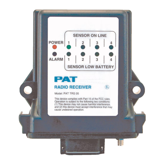
SENSOR ON LINE POW ER 1 ALARM 1 SENSOR LOW BATTERY Model: PAT TRS 05 This device complies with Part 15 of the FCC rules. Operation is subject to the following two conditions: (1) This device may not cause harmful interference, and (2) this device must accept interference that may cause undesired operation. -
Page 12: Repeater
Calibration REPEATER The repeater module is mounted on the boom tip in line of sight to the receiver and the load cell. The main purpose of the repeater is to receive and transmit the load cell ID code of the load cell during operation. - Page 13 Calibration channel/LED 1-4 will be uninstalled and the system will be in normal operating mode.
-
Page 14: Sensor Output Setup
Calibration As the ID button is held (16-28 seconds) through the Install Sensor mode (blinking LEDs1-4) and released at the solid LED, the following actions will occur: Green LED 1 solid: Uninstall sensor 1. Green LED 2 solid: Uninstall sensor 2. Green LED 3 solid: Uninstall sensor 3. - Page 15 Calibration and solid), when the correct green and yellow LEDs are blinking, channel to be calibrated, release the ID button, the following actions will occur: Yellow & Green LEDs 1 Blinking: Calibrate sensor 1 Yellow & Green LEDs 2 Blinking: Calibrate sensor 2 Yellow &...
-
Page 16: Set Zero Point
Calibration Set Zero Point To set the zero point of the load cell, ensure that no load is hung on the load cell, including any hook block, lengths of cable, etc. The software will only allow the load cell zeroed when there is no load on the load cell. - Page 17 Calibration also referred to as working load.
- Page 18 Calibration Test Requirements System tests are to be conducted using an appropriate configured crane and specified load rating chart. For system calibration, three or more test radii or boom angle are to be employed to establish compliance with the accuracy section above. Test loads shall be as near as is practical to minimum, mean, and maximum values within the operating limits.
-
Page 19: Calibration Overview
Calibration CALIBRATION OVERVIEW This section is a basic overview of Section 7 Calibration. Press and hold ID button, release the button at the desired indication (or the number seconds) defined in the following table. The following table can be use as a quick reference guide when calibrating the load cell; however, the Accuracy and Test Requirements must be followed to complete the calibration procedure. -
Page 20: Service And Troubleshooting
Service and Troubleshooting SERVICE AND TROUBLESHOOTING SERVICE Daily maintenance of the system consists of inspecting: 1. The electrical wiring connecting the various parts of the system. 2. If electrical wiring is damaged, it shall be replaced immediately. 3. If the insulation is worn on the electrical wiring or antennas are damaged, these parts shall be replaced. -
Page 21: Repeater
Receiver LED Definition LED Sensor On Line 1 through 4 (Green) Indicates the status of the communication link between sensor 1-4 transmitter and the receiver. Failure of the communication link will cause the Green LED to flash and the signal output will change to the following condition: ... -
Page 22: Maintenance
Maintenance MAINTENANCE The only maintenance required is to change the batteries when required. Also, check the mounting hardware daily to ensure that there is no damage. Replace any damaged parts before operating the crane. BATTERY REPLACEMENT To replace the batteries, remove the 4 screws from the transmitter housing. Install 4 fresh batteries into the proper location and direction as indicated on the battery holder. -
Page 23: Spare Part Numbers
SPARE PART NUMBERS 031-300-050-671 ANTENNA, 918 MHz FOR TRS05ASSEMBLY 060-576 WHIP ELEMENT 031-300-050-672 ANTENNA, 918 MHz MAGNETICBASE 13' long wire 031-300-060-597 RADIO, RECEIVER, TRS05-2SPREAD SPECTRUM W/NEG VOLT OUT... - Page 24 031-300-060-577 Cable Assembly 15’...
- Page 25 Spare Part Numbers 031-300-060-601 CABLE ASSY, 15' 2 COND SS20AWG W/12 SKT DEUTSCH PLUG 031-300-060-596 TRS 05 repeater 031-300-050-688 ANTENNA, 918 MHz RCL 90° 031-300-060-609 SENSOR ASSY, FORCE TRANS. 45KRADIO SPREAD SPECTRUM REV.- 031-300-050-535 CONNECTOR, SMA RIGHT ANGLE M/FREVERSE POLARITY 031-300-060-559 ANTENNA ASSY, 918 MHz WHIP FORLOAD CELL...
- Page 26 Antenna spare parts reiteration 031-300-050-671 ANTENNA, 918 MHz 031-300-050-672 ANTENNA, 918 FOR TRS05ASSEMBLY 060-576 WHIP MHz MAGNETICBASE 13ft long ELEMENT wire 031-300-050-688 ANTENNA, 918 MHz RCL 90° 031-300-060-559 ANTENNA ASSY, 918 MHz WHIP FORLOAD CELL 031-300-050-535 CONNECTOR, SMA RIGHT ANGLE M/FREVERSE POLARITY...
Need help?
Do you have a question about the PAT TRS 05 and is the answer not in the manual?
Questions and answers