
Related Manuals for Elettro CF PLASMA 36

Summary of Contents for Elettro CF PLASMA 36
- Page 1 ELETTRO CF s.r.l. PLASMA 36 COMPRESSOR INVERTER POWER SOURCE art. 481 SERVICE MANUAL 01/11/16...
-
Page 2: Table Of Contents
ELETTRO CF s.r.l. CONTENTS 1 – GENERAL INFORMATION ......................... 3 – Introduction............................3 – General assistance ..........................3 – Safety information..........................3 – Electromagnetic compatibility......................3 2 – SYSTEM DESCRIPTION ..........................4 – Introduction............................4 – Technical specifications........................4 –... -
Page 3: General Information
It is forbidden to attempt to repair damaged electronic boards or modules; replace them with original ELETTRO CF s.r.l. spare parts. 1.3 - Safety information. The safety notes provided in this manual are an integral part of those given in the Instruction Manual. -
Page 4: System Description
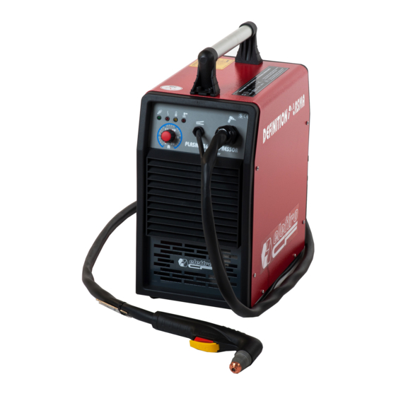
ELETTRO CF s.r.l. 2 - SYSTEM DESCRIPTION 2.1 - Introduction. The PLASMA 26 COMPRESSOR INVERTER is a plasma arc system for cutting electrically conductive materials. It consists of an electronic power source (item 481) and a series of accessories which allow its adaptation to several kinds of uses. -
Page 5: Maintenance
ELETTRO CF s.r.l. 3 - MAINTENANCE WARNINGS ANY INTERNAL INSPECTIONS OR REPAIRS MUST BE CARRIED OUT BY QUALIFIED PERSONNEL. BEFORE BEGINNING MAINTENANCE OPERATIONS, UNPLUG THE POWER SOURCE FROM THE MAINS AND WAIT FOR THE INTERNAL CAPACITORS TO DISCHARGE (1 MINUTE). -
Page 6: Power Source Operation
ELETTRO CF s.r.l. 3.2.2 - Power source operation. NOTE Operations marked with this symbol refer to operator actions. The operations marked with this symbol refer to machine responses that must occur f ollowing an operator action. System shut off and unplugged from the mains. -
Page 7: Troubleshooting
ELETTRO CF s.r.l. 3.3 - Troubleshooting. WARNINGS ANY INTERNAL INSPECTION OR REPAIR MUST BE PERFORMED BY QUALIFIED PERSONNEL. BEFORE REMOVING THE PROTECTION COVERS AND ACCESSING INTERNAL PARTS, DISCONNECT THE MACHINE FROM THE MAINS AND AND WAIT FOR THE INTERNAL CAPACITORS TO DISCHARGE (1 MINUTE). -
Page 8: Power Source Powered, Led A Lit , Fan (9) Stopped
ELETTRO CF s.r.l. 3.3.2 - Power source powered, led (A) lit, fan (9) stopped. FAN (9) TEST. Fan (9) fast-on terminals = 230 Vac, approximately, after closing switch (24). Correct? Make sure that there are no mechanical impediments blocking the fan (9). -
Page 9: Start Button Produces No Effect
ELETTRO CF s.r.l. 3.3.4 – Pressing start button produces no effect. START COMMAND TEST. Press the torch button and check the electrical continuity between torch button contacts on terminals 1-2 of connector J16 on power board (8). Correct? Check wiring between terminals 1 – 2 of J16 and the torch (16). -
Page 10: Gas Flows From The Torch, The Pilot Arc Does Not Light
ELETTRO CF s.r.l. 3.3.6 –Gas flows from the torch, but the pilot arc does not light. Pressing the torch button, the pilot arc lights Correct? Check the conditions of torch consumables. If showing signs of wear, replace. Check wiring between terminals 3 of J16 and torch (16). -
Page 11: List Of Spare Parts
ELETTRO CF s.r.l. 4 - COMPONENTS LIST 4.1 - Power source art. 481 4.2 - Table of components 4.3 - List of spare parts. Essential spare parts. Ref. Description Qty. power board Recommended spare parts. Ref. Description Qty. switch 01/11/16... -
Page 12: Electrical Diagrams
ELETTRO CF s.r.l. 5 – ELECTRICAL DIAGRAMS 5.1 – Power board (8) 5.1.1 - Topographical drawing. 5.1.2 - Connector table. J2 – J3 230 Vac supply voltage input. 1 - 2 230 Vac output for compressor (10). 1 – 2 compressor (10) thermal signal input. - Page 13 Art./Item 481 Ricambi - Spare parts - Ersatzteile – Pièces de rechange - Piezas de repuesto – Peças 01/11/16...
- Page 14 POS. DESCRIZIONE DESCRIPTION STÜCKLISTE DESIGNATION DENOMINACIÓN DESCRIÇÃO SUPPORTO MANICO HANDLE HOLDER GRIFF HALTER SUPPORT MANCHE SOPORTE MANIJA SUPORTE PEGA MANICO HANDLE GRIFF MANCHE MANGO PEGA FASCIONE HOUSING GEHÄUSE CARROSSERIE CARCASA INVÓLUCRO FONDO BOTTOM BODENBLECH FOND FONDO BASE INTERMEDIATE PANNEAU PIANO INTERMEDIO ZWISCHENWANDFLÄCHE PANEL INTERMEDIO PAINEL INTERMÉDIO...
- Page 15 01/11/16...
- Page 16 Farben-Codierung Codification Codificación Codificação cores Codifica colori Wiring diagram elektrische couleurs schéma colores cableado conjunto eléctrico cablaggio elettrico colour code Schaltplan électrique eléctrico de cabos Nero Black Schwarz Noir Negro Negro Rosso Rouge Rojo Vermelho Grigio Grey Grau Gris Gris Cinzento Bianco White...
Need help?
Do you have a question about the PLASMA 36 and is the answer not in the manual?
Questions and answers