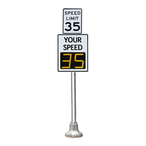
Radarsign TC-400 Operation Manual
Radar speed sign
Hide thumbs
Also See for TC-400:
- Installation manual (11 pages) ,
- Operation manual (16 pages) ,
- Installation manual (15 pages)
Summary of Contents for Radarsign TC-400
- Page 1 Radar Speed Sign Operation Manual (All Models: TC-400, TC-600, TC-1000) © 2005-2021 Radarsign, LLC All Rights Reserved 1 of 16 Radar Speed Sign Operation Manual_MN0025 v21.02...
- Page 2 This Page Left Blank 2 of 16 Radar Speed Sign Operation Manual_MN0025 v21.02...
-
Page 3: Table Of Contents
Password: safety Radarsign, LLC reserves the right to change the specifications without notice. Contact our sales department for special applications and configurations. © 2005-2021 Radarsign, LLC. 3 of 16 Radar Speed Sign Operation Manual_MN0025 v21.02... -
Page 4: Password Notification Card
Thank you for your purchase of this Radarsign® product. NOTE: The Radarsign TC-400, TC-500, TC-600, and TC-1000 series devices comply with Part 15 of the United States Federal Communication Commission (FCC) rules as shipped from the factory. The Radarsign® device must not be opened or modified with the exception of the connection of the solar panel or AC power connections. -
Page 5: Safety Warnings
SAFETY WARNINGS Warning indicates a potentially hazardous situation which if not avoided will result in death or serious injury, and/or property damage. ELECTRICAL SAFETY To reduce the risk associated with electric shock resulting from contacting high voltage AC: Turn power OFF before connecting wiring from our AC powered radar signs to the AC source. To reduce the risk of electric shock related injury resulting from hazardous AC voltage: Portions or this equipment derive power from sources that have high voltage levels. -
Page 6: Wi-Fi Setup
Solar panel current (in Amps): 0 if not charging, up to 3.5 Amps 5) With your smart phone, tablet, or laptop, find the Radarsign Wi-Fi network, RS-xxxxxx (the ‘x’ sequence is the 6 digit serial number of your sign), and connect. - Page 7 10) When the HOME configuration screen opens, it will display the current settings of the radar speed sign. The alert settings and advanced functions available will vary depending on the your sign model and the sign options you purchased. TC-400 TC-600 TC-1000...
-
Page 8: Basic Sign Setup And Configuration
Basic Sign Setup To set up your sign for the first time, you do not need to leave this HOME page. The Sign Status box at the top of the page displays the following: Battery voltage: 13.9+ V is 100%; if voltage •... -
Page 9: Alert Setup
Alert Setup TC-600 TC-400 TC-1000 (1a) (1b) (1c) (1d) Alert 1 1a) Alert 1 Speed: At this speed the Alert 1 display settings will activate. 1b) Display Behavior: Indicates the flash rate behavior of the display. MUTCD flash:55-60 fpm; Slow flash: approx.100 fpm; Fast flash: approx.140 fpm 1c) Display Content: Choose from the options available for your sign model. -
Page 10: Advanced Functions
Choose from BOLD font, full brightness, or lower brightness for LED display. 7) Diagnostics: This tool downloads a diagnostic file to help Radarsign troubleshoot sign issues. Do not run Diagnostics unless directed to by Radarsign Customer Support. 8) Set Defaults: Sets sign to baseline sign settings. -
Page 11: Standard Timers
If you purchased the Streetsmart option, please refer to the Streetsmart Operation Manual for data collection and reporting instructions which can be downloaded from our Customer Re- source Center. https://www.radarsign.com/customer-resource- center/ Password: safety 11 of 16 Radar Speed Sign Operation Manual_MN0025 v21.02... -
Page 12: Appendix A: Relay Switch Option
Appendix A: Relay Switch Option Overview: The TC-600 Interface board allows users to connect the TC-600 Radarsign to external devices. The interface board has two relay outputs (connectors shown in green) and one input (connector shown in blue). The Relay Outputs can be used to power or trigger external devices;... -
Page 13: Speed Activated Relays
Appendix A: Relay Switch Option (cont’d) On the HOME configuration page ensure the Trigger checkbox is checked. Click Set Config. The settings shown on the Trigger Settings screen will now take effect whenever a trigger event is detected (whenever >12V is detected on the trigger input). -
Page 14: Timer Activated Relays
Appendix A: Relay Switch Option (cont’d) Timer Activated Relays Relays can also be configured to close at a certain time using the Timer features. Timer configuration page In the Timer Configuration screen, there is an Output Relay Override box. Enabling these options forces the relay output(s) on for the entire duration of the timer. -
Page 15: Servicing The Interface Board
Appendix A: Relay Switch Option (cont’d) Hyper-Alerts™ Hyper-Alerts™ can be configured to activate at a given speed using the Alert settings in the HOME configuration screen. In the example shown, Beacon Mode is enabled for Alert 2. If a car is traveling over 30 MPH, the Alert 2 settings take over and the Hyper-Alerts™... -
Page 16: Warranty
Replacement parts are covered by the unexpired warranty of the parts they replace. • Claims made under this warranty will be honored only if Radarsign, LLC is notified of a failure within the warranty • period, reasonable information requested by Radarsign is provided, and Radarsign is allowed to verify the cause of the failure.


Need help?
Do you have a question about the TC-400 and is the answer not in the manual?
Questions and answers