Advertisement
Quick Links
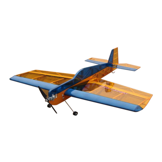
SUPER
KRAFT
PRO-FLY 540
KANGKE INDUSTRIAL USA Inc.
65 East Jefryn Blvd. Deer Park New York 11729
http://www.kangkeusa.com
E-mail:
info@kangkeusa.com
1-877-203-2377
Fax 1-631-274-3296
Warranty: Kangke Industrial USA Inc. guarantees the kit to be free of defects in
both material and workmanship at the date of purchase. This warranty does not
cover any parts damaged by use or modifications. In no case shall Kangke
Industrial's liability exceed the purchase cost of this kit. Since Kangke Industrial
has no control of final assembly and material used by user for final assembly, no
liability shall be assumed or accepted for any damage resulting from the use by
user of final use-assembled products. This kit has been flight tested for normal
use. If the plane will be used for extremely high stress flying, the modeler is
responsible for reinforcing the high stress points. Inspect this kit immediately
Advertisement

Related Manuals for KANGKE INDUSTRIAL SUPER KRAFT PRO-FLY 540


Summary of Contents for KANGKE INDUSTRIAL SUPER KRAFT PRO-FLY 540
- Page 1 1-877-203-2377 Fax 1-631-274-3296 Warranty: Kangke Industrial USA Inc. guarantees the kit to be free of defects in both material and workmanship at the date of purchase. This warranty does not cover any parts damaged by use or modifications. In no case shall Kangke Industrial’s liability exceed the purchase cost of this kit.
- Page 2 This manual is the sole property of Kangke Industrial USA, Inc. Reproducing any part without the consent of Kangke Industrial USA, Inc. is a lawful violation.
- Page 3 you glue or cut anything. How well you assemble this model will have a direct effect on its flight characteristics. Install the landing gear with the With the wing centered, insert a pin supplied straps and screws. on either side of the fuselage to hold it on center during the next alignment steps.
- Page 4 With the elevator centered in the Stick a pin in the center of each CA fuselage insert a pin through the flex hinge, this will keep them on trailing edge directly under the tail. center when the control surfaces are This will hold the alignment for the installed.
- Page 5 servo arm installed. It may be Install the rudder horn the same way, installed with RTV silicone, but with no offset. Fabricate the THICK CA, or screws. control rods with “Z” bends at the servo arm as shown. Locate the components for the control The same process will be used to horn assemblies.
- Page 6 of the fuselage. Small changes in C.G. the runway till the airspeed bleeds off will make large changes in control and the plane settles on. If the landing sensitivity. Adjust elevator throw for is too long add power go around and ½-inch up/down measured at the try again, don’t try to force it to the widest part of the control surface.
Need help?
Do you have a question about the SUPER KRAFT PRO-FLY 540 and is the answer not in the manual?
Questions and answers