Advertisement
Quick Links
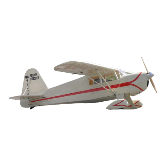
SUPER KRAFT
Rearwin Speedster
Assembly Manual
KANGKE INDUSTRIAL USA Inc.
65 East Jefryn Blvd. Deer Park New York 11729
http://www.kangkeusa.com
E-mail:
info@kangkeusa.com
1-877-203-2377
Fax 1-631-274-3296
Warranty:
Kangke Industrial USA Inc. guarantees this kit to be free of defects in both
material and workmanship at the date of purchase. This warranty does not cover any parts
damaged by use or modifications. In no case shall Kangke Industrial's liability exceed the
purchase cost of this kit. Since Kangke Industrial has no control of final assembly and material
used by user for final assembly, no liability shall be assumed or accepted for any damage
resulting from the use of user-assembled products. This kit has been flight tested for normal
use. If the plane will be used for extremely high stress flying, the modeler is responsible for
reinforcing the high stress points. Inspect this kit immediately after receiving it, report any
missing and damaged parts within 10 business days or your claim may be denied.
1
Advertisement

Related Manuals for KANGKE INDUSTRIAL Rearwin Speedster


Summary of Contents for KANGKE INDUSTRIAL Rearwin Speedster
- Page 1 In no case shall Kangke Industrial’s liability exceed the purchase cost of this kit. Since Kangke Industrial has no control of final assembly and material used by user for final assembly, no liability shall be assumed or accepted for any damage resulting from the use of user-assembled products.
-
Page 2: Super Kraft
Super Kraft 1/4 scale Rearwin Speedster Rearwin Airplanes built the original Rearwin Speedster. The company was founded by Raymond Andrew in 1928 and sold to Empire Ordinance in 1942. The Speedster came in two models, the 6000C powered by a 95 horsepower Cirrus engine and the 6000M powered by a 125 horsepower Menasco. - Page 3 This Manuel is the sole property of Kangke Industrial USA, Inc. Reproducing any part without the consent of Kangke Industrial USA, Inc. is a lawful violation. Because of the large assortment of radios and engines this manual should be considered a guide in those areas.
- Page 4 Remove the upper hatch and the Locate the hardware bag for the main lower pan from the fuselage. gear and install it as shown with four screws and washers {this bag also contains the wing attach screws, and the upper hatch / lower pan screws}. Each hardware bag contains parts for specific components.
- Page 5 Use a felt tip pen to mark the fuselage Open the three holes in the covering outline on the top and bottom of the for the fin as shown. stabilizer. Coat the mating surface of the fin with With a sharp razor knife, cut and a thin layer of epoxy.
- Page 6 Install the lower bracket 2 ¾- inches The distance from the firewall to the in front of the tail wheel bracket. propeller flange or spinner must be Install the lower flying wires, they between 6 7/8-inches and 7 1/4-inches. should be just tight enough to have no endplay but not distort the stabilizer.
- Page 7 Complete the engine installation following the manufacture instructions. Use a felt tip pen to make a dot at the center of each cowl mount 1/2-inch tab. 1 1/8-inch Locate the center of each hinge, and insert a pin through the hinge. Securely tap the cowl in place;...
- Page 8 Assemble the control horn in the Fabricate the rudder end of the cable rudder. Install the tail wheel “T” 2 ¼- in the same way. Adjust the cables so inches behind the hinge line. Install that with the servo and rudder on the tail wheel control springs.
- Page 9 Open the servo arms slots and install Cut a small relief in the belly pan to the servos in its door. Be sure the clear the strut bracket. servo is centered. Relief Run the servo wires through the Install the belly pan with the supplied fuselage and install the servo doors.
- Page 10 Cut and fit the windshield and side With the servo centered install and windows. Install with canopy adjust the push rod. Align the aileron adhesive. Tape securely in place and carefully. allow to cure. Cut the side window 1/8-inch larger than the opening and secure with canopy adhesive.
-
Page 11: Weight And Balance
WEIGHT AND BALANCE Nothing affects the way a plane flies more than weight and balance. Failure to perform this procedure may result in an aircraft that is at best difficult to control, and at worst impossible to fly. Even a small change in the balance point makes a large change in stability. - Page 12 Although the Rearwin will fly well in wind, wait for a nice day. At the field have a helper hold the airplane, following the radio manufactures instructions perform a range check of the radio. Do this with the motor off, start the motor and do it again. Perform this test EVERY TIME YOU GO TO FLY! TRIMING BASIC FLIGHT The Rearwin is NOT a trainer.
Need help?
Do you have a question about the Rearwin Speedster and is the answer not in the manual?
Questions and answers
I have a Super Kraft Rearwin Speedster kit in original box. What’s its worth?