Table of Contents
Advertisement
Quick Links
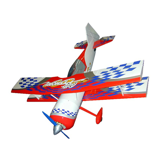
Pitts Python
ARF
ASSEMBLY MANUAL
Kangke Industrial USA, Inc.
49 E. Industry CT, Unit N, Deer Park, NY 11729
http://www.kangkeusa.com
E-mail:
info@kangkeusa.com
Tel: 1-631-274-3058 Fax: 1-631-274-3296
This manual is the sole property of Kangke Industrial USA, Inc. Reproducing any part without the consent
of Kangke Industrial USA, Inc. is a lawful violation.
Warranty: Kangke Industrial USA Inc. guarantees the kit to be free of defects in both material and
workmanship at the date of purchase. This warranty does not cover any parts damaged by use or
modifications. In no case shall Kangke Industrial's liability exceed the purchase cost of this kit. Since
Kangke Industrial has no control of final assembly and material used by user for final assembly, no
liability shall be assumed or accepted for any damage resulting from the use by user of final user-
assembled products. This kit has been flight test for normal use. If the plane will be used for extremely
high stress flying, the modeler is responsible for reinforcing the high stress points. Inspect this kit
immediately after receiving it, report any missing and damaged parts within 7 business days otherwise
the claim may be denied.
Advertisement
Table of Contents

Related Manuals for KANGKE INDUSTRIAL Pitts Python ARF


Summary of Contents for KANGKE INDUSTRIAL Pitts Python ARF
- Page 1 Tel: 1-631-274-3058 Fax: 1-631-274-3296 This manual is the sole property of Kangke Industrial USA, Inc. Reproducing any part without the consent of Kangke Industrial USA, Inc. is a lawful violation. Warranty: Kangke Industrial USA Inc. guarantees the kit to be free of defects in both material and workmanship at the date of purchase.
- Page 2 Congratulations! Kangke Industrial USA, Inc. brings you one of the finest ARF models available. Skilled craftsmen combined with top grade materials and precision jigs have all come together to produce an aircraft with outstanding flight qualities. If you follow the directions carefully the performance of this aircraft will surely please you.
-
Page 3: Important - Please Read
IMPORTANT – PLEASE READ BEFORE YOU GO ANY FURTHER, THERE ARE A FEW ITEMS THAT WE WISH TO BRING TO YOUR ATTENTION SINCE THE MANUAL WAS CREATED, THERE HAS BEEN A LOT OF REAL WORLD FLIGHT TESTING PERFORMED BY A NUMBER OF DIFFERENT OWNER/ PILOTS OVER A PERIOD OF MONTHS. - Page 4 SERVOS Because of the size and weight of the Pitts Python, standard servos do not produce enough torque for high performance aerobatics or 3-D flight. The following are the minimum torque requirements for this level of performance: Ailerons: 80 oz-in. Elevators: 80 oz-in.
- Page 5 Wing wires are NOT required to fly this model if using a 50cc engine BUT are recommended with larger engines. The fuselage and wing attachments for the rigging are included. Due to the many methods of assembly used by modelers, we have not included couplers or the rigging wire.
-
Page 6: Wing Assembly
WING ASSEMBLY Affix servos with required extensions. This sequence will allow for fast assembly of the Attach Control Horn as shown using the 3 small wing assemblies. screws. Attach horn to servo using a 4-40 control rod and Assemble the ailerons to the wing panels as supplied control rod connector. - Page 7 Using a 3/32 or 2.75mm drill bit, drill 4 holes in bottom of outer and center panels where indicated by existing small pilot holes. Drill ONLY until bit enters the metal tube. Install the 4 – 3 X 18mm bolts and washers, It will be tight as you thread through the tube.
-
Page 8: Landing Gear
Take your time cutting out and applying decals. It is time well spent. The belly pan show in the picture above will be installed once you are satisfied that all Landing Gear construction is complete and to your satisfaction. Now it is time to install the landing gear to the I left my pan off till after the first round of fuselage in order to prevent dings in the covering flights just to be sure. - Page 9 RUDDER Insert a pin in the center of the nose deck. Use a string or a ruler, measuring from pin to stabilizer Insert hinges with pins into rudder. outside back edges to square up the stabilizer. Temporarily mount rudder to fin and mark control horn locations which should line up with Our measurement worked out to be 50 ½...
- Page 10 Set and crimp permanently the linkages at the rudder end of the cable. Fuselage/ Upper Wing Cabanes Temporarily connect rudder servo to your radio system to find and hold center. Ensure that Tx trims are neutral. You also should consider blocking the rudder in neutral with a couple of clamps and balsa sticks, Now complete the connection of the pull / pull system to the rudder.
-
Page 11: Wing Struts
Install Fuel Tank Platform Install Fuel Tank platform located directly above landing gear. For the moment, do not tighten the connections. You will do this AFTER you have installed the wires. Bend the connectors so that they are pointing directly at the mating connector. Fin and Stabilizer Cables To provide stability to the tail section and prevent any possibly of tail flutter, wires are... -
Page 12: Engine Installation
The firewall is marked with cross lines for vertical and horizontal. Note that the vertical line is off center. This is designed to allow engine off set while the propeller spinner ends up in center of cowl face. To make the marking job easier, make a template of the engine mount, marking center and drawing similar cross lines as marked on firewall. -
Page 13: Radio Installation
Radio Installation For engines with separate ignitions, you can either install the unit inside the firewall box or You have previously balanced the plane by attached to the firebox sidewall. We suggest you placing the receiver, batteries, etc. loosely in the wrap it in foam to prevent vibration damage and fuselage. - Page 14 CANOPY and TOP HATCH Fit the hatch onto the fuselage. Drill holes, (to match bolt size), through fuselage and hatch hold down tabs. Remove hatch and install blind nuts on back side of tabs. Refit hatch and attach bolts. Attach canopy. (no cutting required). The canopy can be attached using glue such as R/C 56 or simply by using screws.
-
Page 15: Final Assembly
Once the attachments are solid, complete installation with nut assemblies and cotter pins. FINAL ASSEMBLY Attach outer panels of top wing, secure by Additional paint and exterior trim such as decals inserting bolts into the pre-drilled holes on and numbers may be added. Whatever details under-side of wing center section. -
Page 16: Weight And Balance
WEIGHT AND BALANCE For 3 D flying you may consider using:- Nothing affects the way a plane flies more than Aileron 2 ½ inches weight and balance. Failure to perform this Rudder Full throw procedure may result in an aircraft that is at best Elevator Up to 4 inches difficult to control and at worst impossible to fly. - Page 17 If you have followed the procedures in this TRIMING BASIC FLIGHT Manuel you will now be rewarded with one of the finest flying sport models available. All The Pitts Python is NOT a trainer. A true aerobatic maneuvers are at your fingertips and aerobatic aircraft, it goes only where you point it the aircraft will perform them with ease.
- Page 18 Model rolls right, raise left elevator, model rolls ADVANCED FLIGHT TRIM left, raise right elevator. All the following tests should be performed at Pictures of my 50cc powered Pitts 80% power unless noted. Python C.G. Fine Tuning: Roll inverted, neutral elevator to two clicks of down trim, if the model descends move the C.G.
Need help?
Do you have a question about the Pitts Python ARF and is the answer not in the manual?
Questions and answers