Advertisement
Quick Links
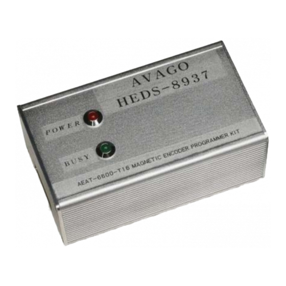
HEDS-8937
AEAT-6600-T16 Magnetic Encoder Programmer Kit
User Manual
1. Introduction
Overview
This user manual describes the Avago HEDS-8937 pro-
grammer kit. The AEAT-6600-T16 magnetic encoder
programming kit features real-time monitoring and
programming of the 32-bit OTP memory within the
AEAT-6600-T16 magnetic encoder IC. The HEDS-8937
kit includes the IC interface hardware that is supported
by PC software. The IC interface hardware is a microcon-
troller system that links the AEAT-6600-T16 encoder to
the PC through a USB cable. This user manual describes
the hardware and PC software setup and gives instruc-
tions on PC software operation.
Features
Bus-powered USB device
On-board 6.5 V programming voltage
Auto-power off when the AEAT-6600-T16 is
removed from the programming socket
Read and write the 32-bit OTP memory
Real-time monitoring of SSI, PWM, ABI or UVW
outputs
Real-time monitoring of MAG_HI and MAG_LOW
signals
This preliminary data is provided to assist you in the evaluation of product(s) currently under development. Until
Avago Technologies releases this product for general sales, Avago Technologies reserves the right to alter prices,
specifi cations, features, capabilities, functions, release dates, and remove availability of the product(s) at anytime.
2. Hardware Component
Unpacking the Unit
The typical packing of the AEAT-6600-T16 magnetic
encoder programming kit is shown in Figure 1.
The kit contains:
1. USB cable
2. AEAT-6600-T16 magnetic encoder programmer
3. IC adapter socket
4. 16-pin ribbon cable
5. Installation CD
Figure 1. Inside the Programmer kit box
Advertisement

Related Manuals for Avago HEDS-8937


Summary of Contents for Avago HEDS-8937
- Page 1 This preliminary data is provided to assist you in the evaluation of product(s) currently under development. Until Avago Technologies releases this product for general sales, Avago Technologies reserves the right to alter prices, specifi cations, features, capabilities, functions, release dates, and remove availability of the product(s) at anytime.
- Page 2 100 mA current limiting circuit to the IC adapter socket. If the current consumption for the encoder being programmed or monitored exceeds 100 mA, the programmer will turn off the power supply to the encoder. Figure 3. HEDS-8937 programmer top cover...
- Page 3 Triangle mark on connector body 15 13 11 16 14 12 10 Pin 1 Figure 4. Programming connector: 16-pin rectangular header connects to the IC adapter socket The pin functions of the programming connector are The 16-pin ribbon cable connects the programmer kit and shown in Table 1.
-
Page 4: Software Installation
The installation CD contains this user manual and the programmer application software. To install the application software, browse to the software folder ‘Avago Magnetic Programmer’ and double-click the ‘Setup.exe’ icon in the folder. The installation will run automatically. Figures 6, 7 and 8 illustrate the software installation. - Page 5 The installation process will continue after the step shown in Figure 8, and fi nally a ‘Setup successful’ pop-up message will indicate completion of the installation. Locate the software by selecting: Start > All Program > Avago > Avago HEDS-8937 Application Kit (by default) or other Start Group specifi ed in the step shown in Figure 8.
- Page 6 4. Software Application 4.1 OTP Programming To run the application software, point to: Start > All Program > Avago > Avago HEDS-8937 Application Kit. After selecting the software, the screen in Figure 9 will appear. The software has three tabs: OTP Programming, Zero Position Programming and IC Monitoring. OTP programming allows programming the OTP memory and zero position programming defi nes the zero position.
- Page 7 4.2 IC Detected After the ‘Detect IC’ button is clicked and IC presence is detected, the screen in Figure 10 appears. Select either one of the programming modes Figure 10. OTP memory confi guration...
- Page 8 The contents of the OTP memory are displayed in the ‘Confi guration Bit in OTP’ frame. The indicated OTP memory is in binary followed by the equivalent hexadecimal value. The symbol ‘/’ separates the binary and hexadecimal values. The SSI ABS measurement is the position value captured when the ‘Detect IC’ button is clicked. ‘Mech Degree’ indicates the equivalent mechanical angle calculated from the SSI ABS value.
- Page 9 If ‘Incremental Output Only’ is selected, the ‘UVW Pole Pair Setting’ / ‘Index Pulse Width’ , ‘Incremental Resolution Setting’ , ‘Zero Position Setting’ , ‘Index Output logic’ , ‘Incremental Mode’ and ‘Incremental Output Enable’ selection options are enabled. The ‘Write OTP’ button will be visible as well. Figure 12.Pop up message for mandatory incremental setting when selecting 16-bit for absolute.
- Page 10 If ‘Both Absolute and Incremental Output’ is selected, all the OTP confi guration settings will be enabled (except the Zero Position Setting). A pop-up message box, as shown in Figure 14 will appear. Figure 14. Pop up message for mandatory incremental setting when selecting 16-bit for absolute. Click button to program settings to OTP memory Figure 15.
- Page 11 After the confi guration setting is complete, click the ‘Write OTP’ button to start OTP programming. The software will compile the data to write to the OTP memory. A confi rmation pop-up message box shows the data to be written to the OTP memory, as shown in Figure 16.
- Page 12 If more than one encoder must be programmed with the same settings, key in the setting only once and click the “Save Confi guration File” button to save the encoder settings. Select “Read From File” to recall the IC settings and then click the “Write OTP”...
- Page 13 For zero position programming, select the centre tab ‘Zero Position Programming’ and the ‘Zero Off set’ frame will be enabled. Either the raw Hex code value for writing to OTP memory or the mechanical angle value can be entered. As shown in Figure 19, once the setting is completed, click the ‘Write Zero Position Off set’...
- Page 14 A confi rmation pop-up message box, shown in Figure 20, will appear before programming begins. When the ‘Yes’ button is clicked, the programming will start. Figure 20. Programming confi rmation pop-up message After programming completes, as shown in Figure 21, the pop-up ‘Zero Off set PROGRAMMING PASS’ message box is displayed.
- Page 15 4.5 AEAT-6600-T16 Encoder Monitoring The monitoring tab displays the real-time output of the AEAT-6600-T16, as shown in Figure 22. The software captures the position measurement at a 12 samples per second rate (update rate may slightly vary depending on the PC). The monitoring software begins automatically when the IC monitoring tab is selected, provided the programmer and encoder is present.
- Page 16 5. Production In-circuit Programming The programming kit performs in-circuit OTP programming of the AEAT-6600-T16 encoder mounted on a target board. To perform in-circuit programming, connect the lines shown in Table 2 to the 16-pin programming header of the target system. Table 2.
- Page 17 6.2 IC Not Present If the AEAT-6600-T16 IC is not present in the programmer, the following message will be displayed. Figure 24. IC not present message There are three possibilities for this condition: 1. The IC adapter socket is not connected to the programmer (via the programming connector). Connect the IC adapter socket to the programmer using the provided 16-pin ribbon cable.
- Page 18 7. Updating the HEDS-8937 Application Kit Firmware Note: To get the up to date both i-Stone iBootloader downloader and HEDS-8937 Application Software please download from Avago product webpage: (http://www.avagotech.com/pages/en/motion_control_encoder_ products/) under part number HEDS-8937 To update the HEDS-8937’s fi rmware you will need: 1.
- Page 19 2. Connect an Avago HEDS-8937 application kit to the PC using one of the USB ports. The downloader software will detect the application kit as shown below. 3. Click the “Boot Mode” button to switch the application kit to bootloader mode.
- Page 20 5. Click the “Open Hex File” button and a fi le selection dialog box will be displayed. Browse and select the new HEX fi le provided. After the HEX fi le is loaded, the “Program/Verify” button will be enabled. 6. Click the “Program/Verify” button to start the fi rmware update process. Once started, the downloader software will perform an erase, program and verify cycle as shown below.
- Page 21 For product information and a complete list of distributors, please go to our web site: Avago, Avago Technologies, and the A logo are trademarks of Avago Technologies in the United States and other countries. Data subject to change. Copyright © 2005-2012 Avago Technologies. All rights reserved.
Need help?
Do you have a question about the HEDS-8937 and is the answer not in the manual?
Questions and answers