Table of Contents
Advertisement
Quick Links
Advertisement
Table of Contents

Related Manuals for Airphx PA2400


Summary of Contents for Airphx PA2400
- Page 1 AIRPHX ® PA2400 User Guide Series 6.0 Rev 4 ● February 22, 2021 AIRPHX 1 | Page...
-
Page 2: Pre-Installation Check List
Pre-Installation Check List Please check the shipping box that your AIRPHX PA2400 arrived in for damage. If any damage is found, please contact your AIRPHX representative prior to installation 855-424-7749 (855-4 AIRPHX). Included in the box o PA2400 o Easy mount wall bracket... -
Page 3: Table Of Contents
Contents Pre-Installation Check List Notice Modes of Operation Operations & Controls Status Indicators Filter Replacement and Reset Procedure Installation Instructions Installation/Unit Overview Installation Procedure Installation Procedure Fig 1 & 2 Installation Procedure Fig 3 & 4 Installation Procedure Fig 5 & 6 Testing –... -
Page 4: Notice
Do not use a cord adapter that defeats the earth ground on the provided power cord. The filters on the PA2400 generally need to be replaced every 30 days. There is a Filter indicator, located on the front of the unit, that will illuminate red as a reminder to change the filters. - Page 5 Do not introduce foreign objects into the unit’s intake or exhaust ports. Keep the air inlets and outlets of the PA2400 clear of obstructions. Do not expose the PA2400 to liquids. Please turn off the PA2400 prior to cleaning around the unit.
-
Page 6: Modes Of Operation
7-day timer. Standby: In standby, the PA2400 7-day timer is on and the timer is in the middle of an OFF-schedule program. The plasma chamber of the unit and the unit’s blower are both off. The Active LED will not be illuminated green. -
Page 7: Operations & Controls
Operations & Controls On/Off Switch The On/Off switch controls the on/off function of the PA2400. The switch will illuminate RED once pressed, turning the PA2400 on. 7 Day Timer Switch The 7-day timer switch controls the on/off function of the 7-day timer. The switch will illuminate green once pressed, turning the timer on. -
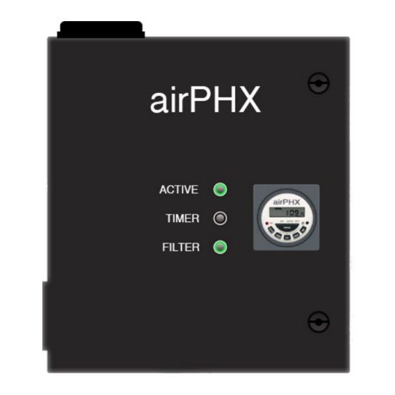
Page 8: Status Indicators
This indicator illuminates green when the unit is in the 7-day timer mode. Filter Indicator/Switch: This indicator will illuminate green at first activation of the PA2400. It will remain green for 30 days at which point it will illuminate red indicating it is time to replace the filter. -
Page 9: Filter Replacement And Reset Procedure
7. To reset the Filter indicator, press the filter reset button located on the front of the unit and hold it for 15 seconds. The Filter indicator will change from red to green indicating the filter reset is completed. The PA2400 will resume operation once this process has been completed. - Page 10 Filter Replacement and Reset Procedure cont. Replacement Filters Additional filters can be purchased by contacting your AIRPHX representative at 855-424-7749 or visiting our website at https://www.AIRPHX.com/shop. Filter Reset Intake Filter 10 | Page...
-
Page 11: Installation Instructions
Installation Instructions The PA2400 mounts to a wall utilizing the provided quick mount wall bracket. This bracket gets mounted to the wall first, then the PA2400 mounts on it. The mounting kit contains: 1. One quick mount wall bracket 2. Four enclosure mounting bolts, pre-installed on the PA2400 3. -
Page 12: Installation/Unit Overview
Below is an overview of the PA2400 and its wall mount bracket. Wall Mount Bracket Washer Wall Wing nut Wing bolt Wall Mount Bracket Enclosure Mounting Bolts Note: Your unit will be black if you purchased an AIRPHX PA2400 Series 6.0. 12 | Page... -
Page 13: Installation Procedure
In the example below, a bolt, flat washer and wing nut are used to secure the wall mount bracket to a drywall surface. 1. Find a central location for the PA2400 in the area you would like to treat. Be mindful of any obstructions that may be within the wall. -
Page 14: Installation Procedure Fig 1
10 Installation Procedure Fig 1 & 2 Fig 1 Fig 2 14 | Page... -
Page 15: Installation Procedure Fig 3
11 Installation Procedure Fig 3 & 4 Wall Mount Holes (V slots) Fig 3 Installed Rear of Enclosure Enclosure Bolts Fig 4 15 | Page... -
Page 16: Installation Procedure Fig 5
12 Installation Procedure Fig 5 & 6 Fig 5 Flat Side of the Bracket Towards Wall Fig 6 16 | Page... -
Page 17: Testing - Replacement Of The Plasma Chamber
If this is a new install and the PA2400 was working without issues for several days before the Active indicator illuminated red, the problem is more than likely temporary. -
Page 18: Plasma Chamber Replacement Process
If resistance is felt during this process, you may want to open the front door to the PA2400 to help guide the plasma chamber into its socket. 10. Replace the exhaust grill taking note of the alignment arrows as shown in Fig An instruction video can be found at https://www.youtube.com/watch?v=cmWUSiliFxw... - Page 19 14 Plasma Chamber Replacement Process cont. Plasma Chamber Exhaust Grill Fig 1A Exhaust Grill Screws Fig 1B 19 | Page...
- Page 20 14 Plasma Chamber Replacement Process cont. Plasma Chamber Plasma Chamber Notch Fig 1C Plasma Chamber Contact Points Notches in Grill Base Fig 1D 20 | Page...
- Page 21 14 Plasma Chamber Replacement Process cont. Inside View of the PA2400 Plasma Chamber Contact Socket Fig 1E Plasma Chamber Contacts Orientation Fig 1F Alignment Arrows 21 | Page...
- Page 22 Some questions concerning operations are set forth below. Q – I have plugged the PA2400 into a 120-volt outlet, but the unit will not turn on. What should I do? A – Verify that the outlet the unit is plugged into has power, the correct voltage and the door to the unit is closed.
- Page 23 Q – What is standby? A – Standby is when the PA2400 stops and the blower is shut off. The unit is silent and appears to be off, but the unit is in fact powered on and waiting for a condition to clear in order to resume operation.
-
Page 24: Warranty
This limited warranty shall not apply to: 1. Cosmetic items. 2. Repairs performed on AIRPHX equipment missing a serial number or with a serial tag that has been altered or defaced. 3. Service calls to correct installation of the equipment or instruct the owners on how to use the equipment. -
Page 25: Disclaimer
AIRPHX representative. Service must be obtained by calling AIRPHX at 1 (855) 4 AIRPHX / 1 (855) 424-7749. THESE SHALL BE THE SOLE AND EXCLUSIVE REMEDIES OF THE BUYER FOR ANY BREACH OF WARRANTY.
Need help?
Do you have a question about the PA2400 and is the answer not in the manual?
Questions and answers