Table of Contents
Advertisement
Quick Links
Advertisement
Table of Contents

Subscribe to Our Youtube Channel
Related Manuals for Magnum Energy MagWeb Wired Ethernet


Summary of Contents for Magnum Energy MagWeb Wired Ethernet
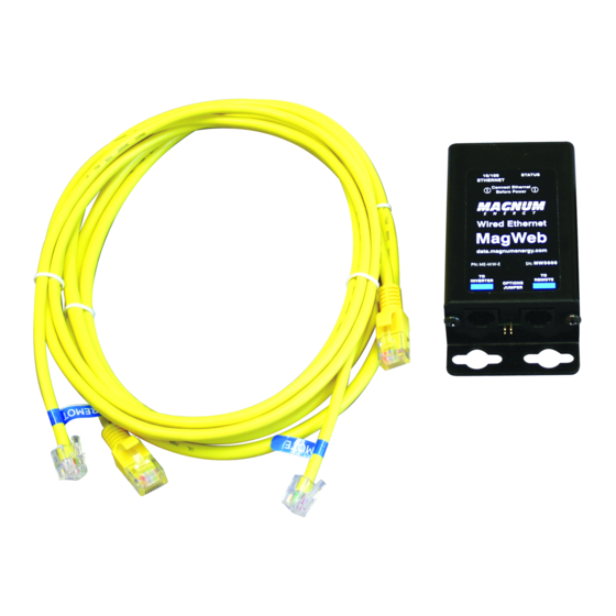
- Page 1 ME-MW-E MagWeb - Wired Ethernet Owner’s Manual...
- Page 2 Restrictions on Use The ME-MW-E may only be used in life-support devices or systems with the express written approval of Magnum Energy. Failure of the ME-MW-E can reasonably be expected to cause the failure of that life-support device or system, or to affect the safety or effectiveness of that device or system. If the ME-MW-E fails, it is reasonable to assume that the health of the user or other persons may be endangered.
-
Page 3: Table Of Contents
3.0 Using data.magnumenergy.com ........6 4.0 Using LED Indicators to Determine MagWeb’s Status ..7 4.1 MagWeb Device LED Status ............7 4.2 MagWeb Wired Ethernet LED Status ..........8 4.2.1 LEDs Below the Ethernet Port ..........8 5.0 Troubleshooting ............10 5.1 Troubleshooting Checklist ............10 5.2 Troubleshooting Questions and Answers ........ - Page 4 Figure 1-1, Illustration of MagWeb Device ..........1 Figure 2-1, MagWeb System Diagram ........... 3 Figure 2-2, MagWeb Dimensions ............5 Figure 4-1, MagWeb Wired Ethernet LED Diagram ........9 List of Tables Table 4-1, MagWeb Device’s LED Indicator Guide ........7 Table 4-2, Functions of LEDs Below the Ethernet Port ......
-
Page 5: Introduction
1.0 Introduction 1.0 Introduction The ME-MW-E (MagWeb Wired Ethernet) is a powerful and cost effective tool for remotely monitoring Magnum inverters and accessories. The MagWeb system connects to the Magnum network and provides live internet moni- toring of the inverter, battery monitor, and the automatic generator start module. -
Page 6: Compatibility And Measurement Channels
Availability, accuracy, and resolution of the measurements are dependent on the particular model(s) of Magnum equipment connected. Contact Magnum Energy to determine if a particu- lar measurement on your inverter or accessories is compatible with the MagWeb system. Some settings and measurements are done inside the remote control. -
Page 7: Installation
S E L E CT I N V CHARG ER I NVERTER SHO RE AG S M ETER SETUP TECH See AGS and BMK Manuals for connection instructions Figure 2-1, MagWeb System Diagram (not to scale) © 2011 Magnum Energy, Inc. -
Page 8: Required Components And Tools
DC return path to the battery – causing permanent damage to all connected accessories on the network. Summation: Always ensure all battery negative circuits are connected before connecting or disconnecting battery positive. © 2011 Magnum Energy, Inc. -
Page 9: Figure 2-2, Magweb Dimensions
(1.5 mm) 4.5 in. (113.4 mm) 2.13 in. (54 mm) 0.315 in. (7.55 mm) Top view 0.2 in. (5.2 mm) 0.39 in. 1.14 in. (10 mm) (29.1 mm) 0.495 in. (12.4 mm) Figure 2-2, MagWeb Dimensions © 2011 Magnum Energy, Inc. -
Page 10: Connecting Magweb To A Local Area Network And The Internet
6ft remote cable with the 50ft remote cable. 2.3 Confi guring the Local Area Network The MagWeb communicates with Magnum Energy’s servers by establish- ing an outgoing TCP/IP connection when data is received. At the default 30-second data interval, the MagWeb system will send approximately 2.5 megabytes of data per day. -
Page 11: Using Led Indicators To Determine Magweb's Status
Check the remote cable; ensure it is connect- ed correctly. BLINKING Important: Ensure the RJ11 connectors are pushed into the correct port; you should feel/ hear a “click” when the connection is made. © 2011 Magnum Energy, Inc. -
Page 12: Magweb Wired Ethernet Led Status
4.0 Using LED Indicators to Determine MagWeb’s Status 4.2 MagWeb Wired Ethernet LED Status 4.2.1 LEDs Below the Ethernet Port Normal operation is amber or green for the Link LED and periodic fl ashing of the Activity LED. Note: Refer to Figure 4-1 (Back View) to determine the positions of the Activity and Link bi-color LEDs within the MagWeb’s Ethernet port. -
Page 13: Figure 4-1, Magweb Wired Ethernet Led Diagram
Bi-Color LED Status Indicator Bi-Color LEDs (Red/Green) Link Activity Back View Ethernet Top View PN: ME-MW-E SN: MW50000 Front View RJ11 Jack RJ11 Jack To Inverter To Remote Figure 4-1, MagWeb Wired Ethernet LED Diagram © 2011 Magnum Energy, Inc. -
Page 14: Troubleshooting
Check the following items before seeking further help: • Is the MagWeb Wired Ethernet connected to an “always on” internet connection? • Did you connect the MagWeb’s Ethernet cable before connecting the remote cable to the inverter or powering the inverter up? •... - Page 15 fi rewall that does not allow outgoing data connections. What if I still have questions? Visit www.magnumenergy.com or call the Magnum Energy offi ces at 425-353-8833. © 2011 Magnum Energy, Inc.
-
Page 16: Specifi Cations
Access to an “always on” internet connection that is capable of sending approxi- mately 2.5 megabytes of data per day. Magnum inverter with a network or remote port. Magnum ME-RC50, ME-ARC50, or ME-RTR controller when other Magnum accesso- ries are connected. © 2011 Magnum Energy, Inc. -
Page 17: Limited Warranty
Magnum Energy shall not be liable for any other losses or damages. Upon request from Magnum Energy, the original purchaser must prove the product’s original date of purchase by a dated bill of sale, itemized... -
Page 18: How To Receive Repair Service
Telephone: 425-353-8833 Fax: 425-353-8390 Email: warranty@magnumenergy.com If returning your product directly to Magnum Energy for repair, you must: • return the unit in the original, or equivalent, shipping container • receive a Return Materials Authorization (RMA) number from the factory prior to the return of the product to Magnum Energy for repair •... - Page 19 Magnum Energy, Inc. 2211 West Casino Rd. Everett, WA 98204 Phone: 425-353-8833 Fax: 425-353-8390 Web: www.magnumenergy.com PN: 64-0055 Rev A...
Need help?
Do you have a question about the MagWeb Wired Ethernet and is the answer not in the manual?
Questions and answers