
Subscribe to Our Youtube Channel
Related Manuals for Magnum Energy ME-BMK


Summary of Contents for Magnum Energy ME-BMK
- Page 1 ME-BMK Battery Monitor Kit Owner’s Manual...
- Page 2 Restrictions on Use The ME-BMK shall not be used in connection with life support systems, life saving or other medical equipment or devices. Using the ME-BMK with this particular equipment is at your own risk.
- Page 3 Figure 3-1, Accessing the Charge Effi ciency Menu Item ......8 Figure 3-2, Adjusting the Charge Effi ciency Menu Item ......9 Figure 4-1, METER Menu Map (ME-BMK Displays)......... 10 Figure 5-1, Accessing the METER Menu Items ........12 Figure 5-2, METER: 03 BM: Meters Selections........13 Figure 5-3, Accessing the METER: 04 BM: Status Display ......
- Page 4 ©2007 Magnum Energy Inc.
-
Page 5: Introduction
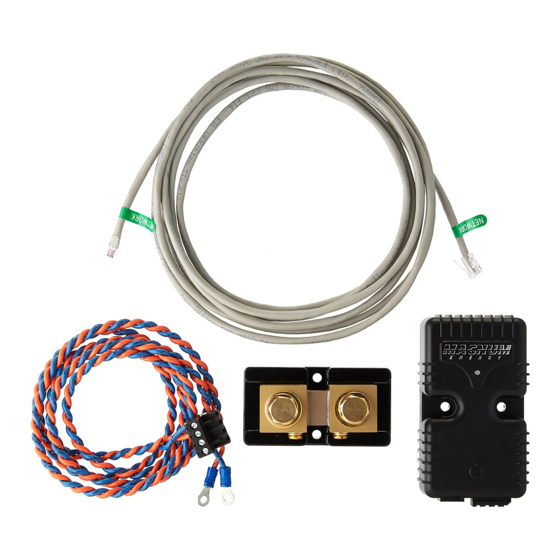
The ME-BMK is easy to install and is designed to be networked with a Magnum Energy inverter/charger using the ME-RC remote to display the information about your battery bank. - Page 6 State Of Charge under all charge and discharge conditions. Theses devices have advantages and disadvantages based on accuracy and ease of use. The Magnum Energy Battery Monitor combines the advantages of these devices with additional information such as monitoring battery tem- perature and calculating battery effi...
-
Page 7: Installation
Installation 2.0 Installation Before installing the ME-BMK, read this entire section to be aware of all as- pects of the installation; then you can thoroughly plan the details to ensure the overall system requirements are accomplished. To assist you in planning and designing your installation; you should review the basic system diagram shown in Figure 2-1. - Page 8 ( 2 am p s ) C ab le (5') sid e s ide (fr o m M E-B M K) B attery Positive D istribution B an k Figure 2-1, ME-BMK Installation Diagram ©2007 Magnum Energy Inc.
-
Page 9: Installation Procedure
Select a location that is dry and away from extreme temperatures to mount the ME-BMK Sense Module and DC shunt; using the supplied #8 x 3/4 screws (x4). Allow ample room to view the LED on the Sense Module, access the screws and bolts on the shunt;... -
Page 10: Figure 2-3, Sense Module Connections
The sense module should now be mounted, refer to fi gure 2-3 for reference during the following steps: 1. Run the communications cable between the ME-BMK Sense Module and the inverter/charger. This cable is a 2-wire, twisted-pair, telephony standard with RJ11 connectors on each end. -
Page 11: Network Connection With Multiple Devices
Installation 2.3 Network Connection with Multiple Devices If you are using more than one Magnum Energy “networked” device, a phone splitter is required to connect the network devices. It is possible to inter- connect the devices in two confi gurations; either a “star” or a “daisy chain”... -
Page 12: Setup
Info: For additional information on navigating the remote display, see the ME-RC Owner’s Manual (PN: 64-0003). Info: See fi gure 4-1, METER Menu Map (ME-BMK Displays) for a complete map of the menu items and adjustable settings available for the ME-BMK using the ME-RC remote control. -
Page 13: Adjusting The Charge Effi Ciency Menu Item
Hour (AH) capacity of the battery bank. After determining the 20-hour AH capacity, adjust this setting slightly on the low side (a smaller value). Info: For more information on this setting, see the ME-RC Owner’s Manual (PN: 64-0003) ©2007 Magnum Energy Inc. -
Page 14: Meter Menu Map
4.0 METER Menu Map The following fi gure is a complete overview of the battery monitor settings and information displays available under the METER menu for the ME-BMK. Familiarize yourself with these menu items to help with menu navigation. M ETER Status…... -
Page 15: Operation
Operation 5.0 Operation This section explains how the ME-BMK battery monitor works and how to operate the ME-RC remote control to obtain information on the battery bank. The LCD displays on the ME-RC related to the battery monitor and the status of the Sense Module’s LED indicator is also explained in this section. -
Page 16: Meter Menu Items And Settings
50% SOC, their effective service life will be con- siderably shorter. This 50% rule has been determined to be the best compromise between available energy and the maximum number of discharge cycles a battery can provide. ©2007 Magnum Energy Inc. -
Page 17: Figure 5-2, Meter: 03 Bm: Meters Selections
This display can help be used as a battery service life indicator. The value is displayed in 0.1k [or 100 amp-hours (“k” equals 1000)] resolution up to a maximum of 6,553.5k amp-hours (6,553,500 amp-hours). The displayed number resets to 0.0k when the Sense Module is disconnected from power. ©2007 Magnum Energy Inc. -
Page 18: Figure 5-4, Meter: 06 Bm: Tech Selections
• BM: No Comm - The BM is not communicating with the remote. This typically means a ME-BMK is not installed in the system. If installed, view the Sense Module LED and use Table 5-1 to help determine the issue. -
Page 19: Figure 5-5, Resetting The Min Dc Value
: rotate to Status… Status… Status… press to press and hold 06 BM: TECH Max DC: ** Max DC: ** select for ~ 5 seconds Figure 5-6, Resetting the Max DC Value ©2007 Magnum Energy Inc. -
Page 20: Led Indicator
LED blinks red and green while going through a self test. Once the self-test is complete, use the table below along with the 04 BM: Status display on the ME-RC to determine the operating status of the ME-BMK. Table 5-1, LED Indicator Guide... -
Page 21: Troubleshooting
The “Min DC” or “Max The Battery Monitor is not communicating, check DC” displays shows that the connections to the Sense Module are 0.0 volts. correct. ©2007 Magnum Energy Inc. -
Page 22: Specifi Cations
DC Shunt Specifi cations Resistance: 0.1 milliohm (500 amps at 50 millivolts) Continuous current: 410 amperes maximum Can take overloads to 500 amps for less than 5 min- Overload current: utes if normally operated at less than 300 amps. ©2007 Magnum Energy Inc. -
Page 23: Limited Warranty
Service and Warranty Info 8.0 Limited Warranty Magnum Energy, Inc., warrants the ME-BMK battery monitor to be free from defects in material and workmanship that result in product failure during normal usage, according to the following terms and conditions: 1. - Page 24 Magnum Energy, Inc. 1111 80th Street SW - Suite 250 Everett, WA 98203 Phone: 425.353.8833 Fax: 425.353.8390 Web: www.magnumenergy.com PN: 64-0013...
Need help?
Do you have a question about the ME-BMK and is the answer not in the manual?
Questions and answers