Table of Contents
Advertisement
Quick Links
Advertisement
Table of Contents

Related Manuals for ASTEL TTM 101C


Summary of Contents for ASTEL TTM 101C
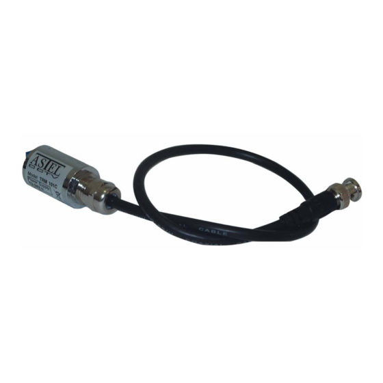
- Page 1 TTM 101C VIDEO TWISTED-PAIR TRANSMITTER OPERATING INSTRUCTIONS v1.0...
- Page 2 CONTENTS Preface ............................... 3 Features..............................3 Block diagram ............................. 3 Principle of operation..........................3 Controls and connectors..........................4 Connections..............................5 Installation..............................5 Appearance ..............................6 Specifications.............................. 6 This unit is produced to comply with Directive 89/336/EEC.
- Page 3 PREFACE The video twisted-pair transmitter TTM 101C is a cable. It has very small dimensions and very low correction amplifier with standard power consumption. choice output asymmetrical video input and symmetrical output impedance allows the use of different kinds of which is adjusted to connect the twisted-pair cables.
- Page 4 CONTROLS AND CONNECTORS FRONT VIEW (1) VIDEO INPUT BNC video input connector with 0.5 m of RG-59 cable to connect the TTM 101C to the video camera. REAR VIEW (1) JUMPER J2 (3) AC/DC POWER SUPPLY Jumper to select the output impedance. When the Terminal block to connect the AC or DC power jumper is removed the impedance is 125 ohm.
- Page 5 CONNECTIONS Be sure to switch-off the power supply unit before connecting to other equipment. Also refer to the instruction manual of the equipment to be connected. VIDEO TWISTED-PAIR RECEIVER POWER SUPPLY INSTALLATION (1) Remove the jumper J1. (0 dB) (2) Insert or remove the jumper J2 to set the correct cable impedance.
- Page 6 APPEARANCE 36.5 SPECIFICATIONS 1 Vpp, 75 , 0.5m RG-59 cable, BNC male connector Video input Video output 2 x 2 Vpp 125 / 90 (J1) Output impedance Freq. response 30 Hz - 5 MHz (0.5 dB) Pre-emphasis +10 dB, 5 MHz (J2) Power supply 12-24 V, AC/DC, 20 mA max.
- Page 8 ASTEL d.o.o., Dutovlje 138, 6221 Dutovlje, Slovenia Tel: +386 5 7310771, +386 5 7310772 Fax:+386 5 7310789 E-mail: sales@astel-cctv.com Web: www.astel-cctv.com...
Need help?
Do you have a question about the TTM 101C and is the answer not in the manual?
Questions and answers