Table of Contents
Advertisement
Pulseo Series
User's Manual
High Peak Power, Diode Pumped, Q-Switched Laser System
Pulseo 355-20
Pulseo 355-10
Pulseo 355-8-300
Pulseo 532-34
This laser product is intended to be sold to a
manufacturer of OEM products for use as a
component (or replacement thereof) in those
products. As such, this product is exempt from
performance standards of United States Code
of Federal Regulations, Title 21, Chapter 1 –
Food and Drug Administration, Department of
Health and Human Services, Subchapter J –
Parts 1040.10 (a), (1) or (2).
Spectra-Physics
3635 Peterson Way
Santa Clara, CA 95054
Part Number 90041652
October 2011
Revision B
Advertisement
Chapters
Table of Contents

Related Manuals for Spectra-Physics Pulseo Series


Summary of Contents for Spectra-Physics Pulseo Series
- Page 1 Pulseo Series User’s Manual High Peak Power, Diode Pumped, Q-Switched Laser System Pulseo 355-20 Pulseo 355-10 Pulseo 355-8-300 Pulseo 532-34 This laser product is intended to be sold to a manufacturer of OEM products for use as a component (or replacement thereof) in those products.
- Page 2 Every effort has been made to ensure that the information in this manual is accurate. Spectra-Physics further reserves the right to revise this manual and to make changes to its contents at any time, without obligation to notify any person or entity of such revisions or changes.
-
Page 5: Preface
Preface About this Guide The Spectra-Physics Pulseo system is a solid-state, Q-switched laser that produces laser pulses at adjustable repetition rates from 1 Hz to 400 kHz. The system is comprised of the Pulseo laser head, the D-Series power supply, and a closed-loop chiller. - Page 6 “Form for Problems and Solutions” is our feedback form, which you can use to report problems with our instruments or documentation, submit comments, suggest new features, or request more information. “Notes” provides space to keep track of the service history for your Pulseo laser. Preface...
-
Page 7: Environmental Specifications
EN-60309, “Plug, Outlet and Socket Couplers for Industrial Uses,” listed in the official Journal of the European Communities. Environmental Specifications The environmental conditions under which the laser system function are listed on the Spectra-Physics website at http://www.newport.com/pulseo. These specifications reflect indoor use conditions. Feature Specification... - Page 8 Modifications to the laser system not expressly approved by Spectra-Physics could void your right to operate the equipment. viii Environmental Specifications...
-
Page 9: Warning Conventions
Warning Conventions Warning Symbols The following symbols are used throughout this manual to draw your attention to situations or procedures that require extra attention. They warn of hazards to your health, damage to equipment, sensitive procedures, and exceptional circumstances. All messages are set apart by a thin line above and below the text as shown here. - Page 10 Do not touch. Appropriate laser safety eyewear should be worn during this operation. Refer to the manual before operating or using this device. Serviceable only by Spectra-Physics factory trained personnel. Factory Trained Warning Conventions...
-
Page 11: Standard Abbreviations
Standard Abbreviations The following units, abbreviations, and prefixes are used in this Spectra-Physics manual. Unit Abbreviations Quantity Unit Abbreviation mass kilogram length meter time second frequency hertz force newton energy joule power watt electric current ampere electric charge coulomb electric potential volt Ω... - Page 12 Prefixes Prefix Power Abbreviation Prefix Power Abbreviation tera milli giga micro μ mega nano kilo pico deci femto centi atto Abbreviations and Acronyms Abbreviation Description alternating current ACGIH American Conference of Governmental and Industrial Hygienists ALPS active laser purification system ANSI American National Standards Institute acousto-optic modulator...
- Page 13 Abbreviation Description SCPI Standard Commands for Programmable Instruments second harmonic generator third harmonic generator ultraviolet volts, alternating current volts, direct current λ wavelength WEEE waste electrical and electronic equipment Standard Abbreviations xiii...
- Page 14 Standard Abbreviations...
-
Page 15: Table Of Contents
Table of Contents Preface ..............v Environmental Specifications . - Page 16 Laser Safety Standards ......... . .2-13 Equipment and Training .
- Page 17 Front Panel Features ..........4-4 Rear Panel Features .
- Page 18 Chapter 7: Maintenance ....... 7-1 Filter Cleaning Recommendations ........7-1 Cleaning the D-Series Power Supply Filters and Grills.
- Page 19 Notes............Notes-1 Index .
- Page 20 Table of Contents...
-
Page 21: List Of Figures
List of Figures Figure 1-1: Pulseo laser head and power supply ....... . 1-1 Figure 2-1: Safety warning labels (EN 60825-1: 2007, ANSI Z136.1 Section 4.7) . - Page 22 Figure 6-7: Generating bursts ..........6-17 Figure 6-8: Burst with reduced pulse energy .
- Page 23 List of Tables Table 1-1: Pulseo system patents ......... . . 1-4 Table 2-1: Maximum emission levels .
-
Page 24: List Of Tables
xxiv List of Tables... -
Page 25: Chapter 1: Introduction
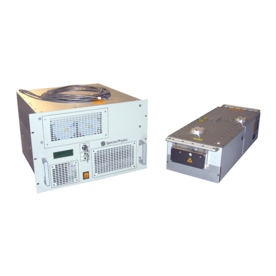
Figure 1-1 Pulseo laser head and power supply The Spectra-Physics Pulseo system is a solid-state, Q-switched laser that produces laser pulses at adjustable repetition rates from 1 Hz to 400 kHz. The system is comprised of the Pulseo laser head, the D-Series power supply, and a closed-loop chiller (Figure 1-1, chiller not shown). -
Page 26: Pulseo Laser System
Pulseo Laser System Field-serviceable product design Low cost of operation Ample headroom and tight process control Continuous improvement process for ongoing product improvement Thorough new product testing and qualification FMEA design process Long SHG and THG crystal life EternAlign™ solder free optic mounts Active Laser Purification System™... -
Page 27: System Control
System Control A fiber-coupled diode laser module is often referred to simply as a “diode” in the context of this manual, for example, “the diode current.” The D-Series power supply also contains the control logic and electrical power modules for the system, as well as systems for removing waste heat from the two or four laser diode modules. -
Page 28: Patents
Patents Patents Pulseo systems are manufactured under one or more of the following patents. Table 1-1 Pulseo system patents Pulseo 355-20A Laser Head 4,829,529 5,812,308 5,608,542 6,504,858 6,734,387 5,080,706 5,835,513 5,812,583 6,246,706 6,822,978 5,127,068 5,410,559 5,999,344 6,373,565 5,412,683 5,577,060 5,561,547 6,421,573 5,436,990 5,907,570... -
Page 29: Chapter 2: Laser Safety And Compliance
Important Safety Notes Before unpacking, setting up, or operating the Pulseo laser or any of its components, review the safety information in this chapter carefully. Refer to the Pulseo Series Service Manual for instructions on unpacking and installing your system. -
Page 30: Maximum Emission Levels
Maximum Emission Levels Maximum Emission Levels The maximum emission levels possible for the Pulseo laser are listed in Table 2-1. Use this information to select laser safety eyewear and to implement appropriate safety procedures. These values do not imply actual system power or specifications! Table 2-1 Maximum emission levels Emission Wavelength... -
Page 31: Safety Device Locations
A white emission indicator located on the top of the laser near the beam exit end (Figure 2-3) An “emission” notification that is displayed on the monitor of the control PC when the control software provided by Spectra-Physics or properly written control software is used and the ON command is given A green... -
Page 32: Safety Interlocks
Safety Device Locations Emission Indicator Shutter Indicator Figure 2-3 Pulseo laser head indicators When any of these emission indicators are on, power is being supplied to the diode lasers, and Pulseo emission is present or imminent. To warn personnel, these indicators turn on about 3 seconds before actual emission occurs. -
Page 33: Shutter
There are no user-serviceable parts inside the laser head. Refer all service to qualified personal. Power Supply Only a Spectra-Physics trained and qualified repair technician should open the power supply. A warning label is attached to the power supply (Figure 2-9). Labels also warn of high voltage and state that power must be off before any covers are removed. -
Page 34: On/Off Controls And Power Indicator
Operating the Laser via a User-Created GUI The shutter is a safety device and is not to be used as a process control device. Refer to “Control Methods” for process controls. Do NOT apply voltage to this circuit! Doing so can damage the shutter! On/Off Controls and Power Indicator When the AC power is turned on, the on/off rocker switch provides power to the... -
Page 35: Crdh Drawings And Labels
CRDH Drawings and Labels CRDH Drawings and Labels The following figures are control drawings for CDRH compliance. D-Series Power Supply Safety Devices Figure 2-6 D-Series power supply safety devices, front (Model D400) Laser Safety and Compliance... -
Page 36: Figure 2-7 D-Series Power Supply Safety Devices, Rear (Model D400)
CRDH Drawings and Labels Figure 2-7 D-Series power supply safety devices, rear (Model D400) Laser Safety and Compliance... -
Page 37: Safety Warning Labels
CRDH Drawings and Labels Safety Warning Labels Label Illustrations See “Label Placement” for the locations of the numbered labels on the device. 363 5 P et erson Way , S ant a Clar a, CA 950 54 VISIBLE AND INVISIBLE* MANUFACTURED IN U.S.A. -
Page 38: Figure 2-9 Pulseo Laser Head Radiation Control Features, Top
CRDH Drawings and Labels Label Placement See “Label Illustrations” for larger images of the numbered items. Figure 2-9 Pulseo laser head radiation control features, top Figure 2-10 Pulseo laser head radiation control features, side Figure 2-11 Pulseo laser head radiation control features, front (left) and rear (right) 2-10 Laser Safety and Compliance... -
Page 39: D-Series Power Supply Radiation Control
CRDH Drawings and Labels D-Series Power Supply Radiation Control s e r is s io n R IA IN T IS S Figure 2-12 D-Series power supply radiation control features (Model D400) Laser Safety and Compliance 2-11... -
Page 40: Ce Declaration Of Conformity
CE Declaration of Conformity CE Declaration of Conformity Spectra-Physics, a Newport Corporation Brand Peterson Way Santa Clara, CA 95054 United States of America declare under sole responsibility that the Pulseo Family of Laser Systems Manufactured after March 1,2011, meets the intent of EMC Directive 2004/108/EC for Electromagnetic Compatibility and 2006/95/EC for the Low Voltage Directive. -
Page 41: Weee Recycling Label
13 August 2005. At this time, regulations for the disposal of waste electrical and electronic equipment vary within the member states of the European Union. Please contact a Newport / Spectra-Physics representative for information concerning the proper disposal of this product. -
Page 42: Equipment And Training
Additional Safety Resources Washington, DC 20210 Tel: (202) 693-1999 Website: http://www.osha.gov A Guide for Control of Laser Hazards, 4th Edition, Publication #0165 American Conference of Governmental and Industrial Hygienists (ACGIH) 1330 Kemper Meadow Drive Cincinnati, OH 45240 Tel: (513) 742-2020 Website: http://www.acgih.org/home.htm Laser Institute of America... - Page 43 Additional Safety Resources Photonics Spectra Buyer's Guide Photonics Spectra Laurin Publications Berkshire Common PO Box 4949 Pittsfield, MA 01202-4949 Tel: (413) 499-0514 Website: http://www.photonics.com Laser Safety and Compliance 2-15...
- Page 44 Additional Safety Resources 2-16 Laser Safety and Compliance...
-
Page 45: Chapter 3: Pulseo Laser Description
This manual, a packing slip listing all the parts shipped, and an accessory kit containing the items listed below are shipped along with the laser system. Verify that all items are present. (Spectra-Physics part numbers are listed in Chapter 10, “Field Replaceable Units (FRUs)”) (1) 2.5 m (8 ft.) 3-wire AC power cord, no plug (the customer must provide and... -
Page 46: Chiller
It is designed to protect ferrous metals and copper alloys from corrosion. It is nitrite free and it minimizes the problems associated with bacteria control. Nalco can be ordered directly from Spectra-Physics, P/N 1607-0546. See Appendix B, “Nalco MSDS,” for more information about the Nalco product. -
Page 47: Q-Switching
Key Features Tripling”) are especially susceptible to absorption by water vapor, it is important that the laser cavity be continuously purged with clean, dry air. The D-Series power supply contains a system purge for this reason; refer to “Active Laser Purification System (ALPS).”... -
Page 48: Laser Power Monitor
Key Features THG Shutdown Option: In addition to the THG Spot Life Warning, and the THG Spot Overuse Error, there also exists a programmable fault feature within the Pulseo software to halt the laser if the THG spot life exceeds a user-defined limit. In the event of this case, the diodes are automatically turned OFF immediately, and it is not possible to turn them back ON again until the THG crystal spot is changed. -
Page 49: E-Pulse™ Constant Energy Feature
Key Features Safety Mode is the default mode, and allows the shutter to be re-opened only when all conditions and inputs that caused the shutter to close have been removed, and then the OPEN serial command is issued. Process Mode is enabled using the SHUTLATCHING:0 command (described in Appendix A, “Serial Command Interface”) closes the shutter when pins 6 and 7 of interface are opened, and opens the shutter again immediately LASER CONTROL... -
Page 50: Condensation Alarm
System Component Descriptions Condensation Alarm Operating the Pulseo laser system in the proper ambient conditions is essential to ensure long life. In addition to internal humidity monitors, a condensation detector is mounted under the diode coldplate. As the ambient conditions approach the condensation dewpoint, the sensor trips and prevents the user from turning the laser diode emission ON. -
Page 51: Laser Head
Non-Optical Specifications Conduction path to cool the single emitters Electrical circuit to power the emitters Protection for both the single emitters as well as the user Laser Head The Pulseo laser head contains its own controller that executes specific commands related to laser head operation, such as controlling the harmonic crystal temperature. -
Page 52: Fuse Requirements
Outline Drawings Table 3-1 Power and cooling Feature Specifications AC power input 100 to 240 VAC Maximum power consumption (absolute) 750 W Fuse Requirements The D-Series power supply incorporates double-pole neutral fusing for operation from 100 to 240 VAC. These two fuses are located on the rear panel of the power supply and can be accessed using a standard screwdriver. -
Page 53: Figure 3-2 Pulseo Laser Head Outline, Side View
Outline Drawings Figure 3-2 Pulseo laser head outline, side view Figure 3-3 Pulseo laser head outline, bottom view Figure 3-4 Pulseo laser head outline, front (left) and rear (right) view Pulseo Laser Description... -
Page 54: Figure 3-5 Laser Head Mounting Holes
Outline Drawings See Detail B Laser Mounting 9.000 in. English Mounting Pattern 22,500 cm Metric Mounting Pattern Bottom View 30,00 cm Metric Mounting Pattern 12.000 in. English Mounting See Detail A Pattern Detail A 30,00 cm 9.000 in. Metric Mounting English Mounting Pattern Pattern... -
Page 55: Power Supply
Outline Drawings Power Supply All dimensions in the figures are inches over mm. Figure 3-6 D-Series power supply outline, front Figure 3-7 D-Series power supply outline, side Pulseo Laser Description 3-11... -
Page 56: Block Diagrams
Block Diagrams Block Diagrams Electrical Diagrams (Interlock) Laser Head Interlock Monitor Remote Interlock Monitor Key Switch User Interlock Monitor System Interlock Monitor Fuse Monitor +24 Vdc Remote Laser Head Fuse User System (Non-funtional) Interlock Switch InterLock InterLock Laser Diode + 3.3 Vdc Keep Alive Passbank Enable... - Page 57 Block Diagrams Pulseo Laser Head Rear Panel EEPROM Fiber-optic Cables (2 or 4) Flash Memory See the Interconnect Drawing in Chapter 6 for details on making the system connections. D-Series Power Supply Q-Switch Rear Panel RF Power (Model D400 shown) Cables (x2) SHUTTER RF 1...
- Page 58 Block Diagrams 3-14 Pulseo Laser Description...
-
Page 59: Chapter 4: Controls, Indicators, And Connections
4: Controls, Indicators, and HAPTER Connections This chapter describes the external controls, indicators, and connections of the Pulseo laser system. The serial command language and the analog signals used to control the system are described here and in Appendix A, “Serial Command Interface.” Pulseo Laser Head Controls There are no controls on the Pulseo laser head itself;... -
Page 60: Connectors
Pulseo Laser Head Table 4-1 Pulseo laser head indicators Indicator Description Emission indicator (white) Turns on after the ON command is issued; laser emission is possible 3 seconds later. The indicator remains on during laser emission and turns off when emission is terminated. -
Page 61: Table 4-3 Pulseo Laser Head Shutter Control Connector Pins
Pulseo Laser Head Table 4-2 Pulseo laser head rear panel connectors (Continued) Connector Description RF power input cable connectors Connections for the RF power from the D-Series power supply for the Q-switches. (2, SMA) ALPS air inlet and return Connections for the input and return hoses to the recirculating active laser purification connectors (2) system (ALPS) inside the D-Series power supply. -
Page 62: D-Series Power Supply
D-Series Power Supply Table 4-3 Pulseo laser head shutter control connector pins (Continued) Type Pin Name Description No connection No connection No connection D-Series Power Supply All power supply controls and indicators are located on the front panel, while all the connections are on the rear panel. -
Page 63: Table 4-4 D-Series Power Supply Front Panel Features
D-Series Power Supply Table 4-4 D-Series power supply front panel features Control Description ALPS access panel Provides access to the active laser purification system (ALPS) inside the D-Series power supply. Refer to “Changing the ALPS Filters” for instructions on when and how to change the desiccant in this unit. -
Page 64: Rear Panel Features
D-Series Power Supply Rear Panel Features Top Panel Controls are described as they appear on the top panel shown in Figure 4-5, from top to bottom, left to right. Laser Control Enable In Trigger In Sync Out Shutter Control AOM RF Connector Connector Connector... - Page 65 D-Series Power Supply Table 4-5 D-Series power supply top rear panel controls (Continued) Control Description ENABLE IN Enables laser pulsing (opens the gate) when a TTL low level signal is applied (the default condition is TTL high). This is a non-opto-isolated alternative to using pins 8 and 9 of the Laser Control interface.
-
Page 66: Opto-Isolated Connections Of The Laser Control Interface
Opto-Isolated Connections of the LASER CONTROL Interface Table 4-5 D-Series power supply top rear panel controls (Continued) Control Description USB connector Used in conjunction with the LASER CONTROL port to control the laser system. Alternatively, the SERIAL COM port (see below) can be used instead. Refer to Appendix A, “Serial Command Interface,”... -
Page 67: Opto-Isolator Description
Opto-Isolated Connections of the LASER CONTROL Interface Opto-Isolator Description In the user-supplied controller, a resistance value has to be selected so that no more than 5.1 V is applied to a pair of opto-isolated pins of the connector (see LASER CONTROL Table 4-8). -
Page 68: Table 4-8: Laser Control 25-Pin Connector Descriptions
Opto-Isolated Connections of the LASER CONTROL Interface Table 4-7 Opto-isolator output parameters Parameter Minimum Typical Maximum Supply voltage (pins 5, 3) 4.5 V 5.5 V Supply current (pins 5, 3) 36 mA 42 mA all outputs in use Low-level output voltage 0.2 V 0.6 V Low-level input current... - Page 69 Opto-Isolated Connections of the LASER CONTROL Interface Table 4-8 25-pin connector descriptions (Continued) LASER CONTROL Type Pin Name Description Input Shutter command Opto-isolated signal. Opens and closes the shutter. Apply a positive voltage with respect to pin 13 to close the shutter (high = shutter closed).
- Page 70 Opto-Isolated Connections of the LASER CONTROL Interface Table 4-9 IBM-PC/AT serial port pinout Computer or Terminal Model D400 RS-232-C Signal Name Signal Pin No. (9-Pin) Pin No. Signal Transmit data Receive data Signal ground Protective ground SHELL SHELL + 24 V 3 Wiper 2 N.O.
-
Page 71: Table 4-10 D-Series Power Supply Bottom Rear Panel Connections
Opto-Isolated Connections of the LASER CONTROL Interface Table 4-10 D-Series power supply bottom rear panel connections Connection Description Fiber-optic cables (2 or 4) Delivers optical pump power from the laser diodes to the Pulseo laser head. The fiber-optic cables on the D-Series power supply are not permanently attached to the diode modules inside the power supply and can be replaced in the field by a qualified service engineer if damaged. -
Page 72: Chiller
Chiller Chiller Table 4-11 lists the chiller requirements for the Pulseo system. Refer to the chiller manual for complete specifications. Table 4-11 Chiller output specifications Feature Specifications Fluid temperature 20°C Fluid flow rate 3.8 liter/min @ 210 kPa (1 gpm @ 30 psi) 4-14 Controls, Indicators, and Connections... -
Page 73: Chapter 5: Preparing For Operation
5: Preparing for Operation HAPTER Installing the USB Driver and User GUI Software For startup and maintenance, the Pulseo system can be controlled using the GUI control software provided with the system. However, for long-term, day-to-day operation, the laser system should be controlled remotely using software written by the user that is based on the Pulseo command language described in Appendix A, “Serial Command Interface.”... -
Page 74: Figure 5-1 Preinstaller Icon
Installing the USB Driver and User GUI Software 3. Double-click the PreInstaller icon. Figure 5-1 PreInstaller icon 4. In the Install Driver screen, click Install. Figure 5-2 Install Driver screen 5. Click through any other screens that come up and accept the default installation directory. -
Page 75: Installing The Pulseo Gui Control Software
Setup.exe during installation. Figure 5-5 Setup icon The software creates the directory C:\Program Files\Spectra-Physics\Pulseo on the drive of your choice (the default drive is ), and installs itself in that location. It also installs run-time components into the directory. C:\windows\system The software places a Pulseo icon on the desktop. - Page 76 Installing the USB Driver and User GUI Software Preparing for Operation...
-
Page 77: Chapter 6: Operation
This chapter describes the operation of the Pulseo system, including system notices. Read Chapter 2, “Laser Safety and Compliance,” before turning on the Pulseo system. Spectra-Physics Pulseo lasers are Class IV — High-Power Lasers whose beams are, by definition, safety and fire hazards. Take precautions to prevent accidental exposure to both direct and reflected beams. -
Page 78: Figure 6-1 Pulseo Gui Control Panel, 532 System
Pulseo GUI Control Panel Figure 6-1 Pulseo GUI control panel, 532 system Figure 6-2 Pulseo GUI control panel, 355-20 system Operation... -
Page 79: Figure 6-3 Pulseo Gui Control Panel, 355-10 System
Pulseo GUI Control Panel Figure 6-3 Pulseo GUI control panel, 355-10 system The GUI controls shown in Figure 6-1, Figure 6-2, and Figure 6-3 are described in Table 6-1 in order from left to right, top to bottom. Enter control values by either typing them directly into the field or by using the up/down buttons to the left of each field. - Page 80 Pulseo GUI Control Panel Table 6-1 Controls on the Pulseo GUI control panel (Continued) Control Description GATE control and Allows the operator to open and close the gate and to view its status. Click the toggle switch to indicator open and close the gate; its status is displayed by the indicator. The color of indicator changes from black to green when the gate is open, and back to black when it is closed again.
- Page 81 Pulseo GUI Control Panel Table 6-1 Controls on the Pulseo GUI control panel (Continued) Control Description SHG TEMPERATURE Allows the operator to change the SHG temperature set value between 1 and 4095 counts. control This value was optimized by the factory, and the optimal SHG temperature should remain within ±...
-
Page 82: First Power Up And Initial Startup
If you have not already done so, refer to the chiller installation instructions in the Pulseo Series Service Manual before starting the chiller for the first time. The chiller must be flushed first, then filled with coolant (Nalco coolant or distilled water) prior to use. - Page 83 Pulseo system is ready to accept commands through either the USB or serial interface. Spectra-Physics recommends that the harmonic crystals be allowed to warm before the diodes are energized. Allow 20 minutes for the harmonic crystals to stabilize before turning the diodes on.
- Page 84 First Power Up and Initial Startup THG Spot Life Warning: This is an automatic warning message issued by the Pulseo software when the THG crystal spot has exceeded 1,000 hours of operation. This is event Code 70 (THG HOURS WARNING). It is recommend shift the THG crystal spot as soon as practical.
- Page 85 First Power Up and Initial Startup 6. Before requesting laser output, verify that the Pulseo operating parameters match the parameters listed on the Ship Report delivered with the system: a. Enter the query ?Q in the Command Input field to check the Q-switch frequency setting.
-
Page 86: Turn On / Turn Off Sequence
Turn On / Turn Off Sequence If the measured output power does not agree with that on the Ship Report, it might be necessary to optimize the temperature of the harmonic crystals (i.e., to temperature tune the crystals). See “Tuning Harmonic Crystal Temperatures.” 12. -
Page 87: Mode 1: Using Serial Commands
The Shutter Control Interface Table 6-2 Shutter configurations (Continued) Configuration Parameters Shutter Behavior Notes SHT:1 SHT:1 Voltage on pin 12 LC No voltage on pin 12 LC Open pins 1, 6 SC Short pins 1, 6 SC; either SHT:1 or provide falling edge on pins 12, 13 LC Open pins 6, 7 LC Short pins 6, 7 LC;... -
Page 88: Mode 3: Via The Shutter Control Connector On The Laser Head
The Shutter Control Interface If the interface is used, the connector LASER CONTROL ENABLE IN must be shorted or terminated with a 50 W BNC plug (or the GEXT variable must be set to zero to disable the ENABLE IN connector . -
Page 89: Adjusting Uv Pulse Energy By Pulse Width Modulation
Adjusting UV Pulse Energy by Pulse Width Modulation Adjusting UV Pulse Energy by Pulse Width Modulation Use the duty-cycle or pulse-width modulation (PWM) method to control the Pulseo UV pulse energy on a pulse-by-pulse basis. To set up pulse-width modulation: 1. -
Page 90: Case 1: Full-Pulse Energy
Adjusting UV Pulse Energy by Pulse Width Modulation Case 1: Full-Pulse Energy One pulse-cycle is illustrated in Figure 6-4 (pulse period 29.7 μsec). The duty cycle is approximately 50 percent. The optical pulse is emitted approximately 9 microseconds AFTER the falling edge of the 50 percent waveform. Figure 6-4 Full-pulse energy 6-14... -
Page 91: Case 2: Reduced-Pulse Energy
Adjusting UV Pulse Energy by Pulse Width Modulation Case 2: Reduced-Pulse Energy Case 2 increases the blue waveform duty cycle to approximately 80 percent. This pushes out the falling edge, delaying the generation of the pulse. Figure 6-5 Reduced-pulse energy Operation 6-15... -
Page 92: Case 3: Minimal Pulse Energy
Adjusting UV Pulse Energy by Pulse Width Modulation Case 3: Minimal Pulse Energy Case 3 increases the duty cycle of the drive to maximum limit. Figure 6-6 Minimal pulse energy 6-16 Operation... -
Page 93: Case 4: Generating Bursts
Adjusting UV Pulse Energy by Pulse Width Modulation Case 4: Generating Bursts The PWM signal introduced into the ENABLE BNC can be used to generate bursts. Figure 6-7 Generating bursts Operation 6-17... -
Page 94: Case 5: Burst With Reduced Pulse Energy
Control Methods Case 5: Burst with Reduced Pulse Energy Figure 6-8 Burst with reduced pulse energy Control Methods The Pulseo system can be controlled using the provided GUI, or signals applied to the interface, or by a combination of serial commands and analog signals LASER CONTROL provided by a host system. -
Page 95: External-Triggering Timing Nomenclature
Control Methods Although the laser is capable of pulse repetition rates from 1 Hz to 400 kHz, specified output power is for a 100 kHz pulse rate. The samples below arbitrarily call for a 150 kHz pulse rate. External-Triggering Timing Nomenclature 0.5 µs <... -
Page 96: Method B: Internal Pulse Trigger: External Gating Via Enable Bnc
Control Methods Gate 0 Internal Trigger and Internal Gate TRIGGER Method A Laser Figure 6-10 Internal triggering operating method Table 6-3 Internal gating operating method summary (A) Internal pulse trigger: internal gating Advantage Easy to set up (no analog port connections required); safe, fast gating Main commands Q<n>... -
Page 97: Method C: Internal Pulse Trigger: External Gating Via Laser Control
Control Methods Case B: Internal Trigger, External Enable (GATE) With the internally generated oscillator enabled (i.e., Q:100000, the Q-switch is continuously open), use the BNC jack to modulate the pulse train. ENABLE IN Enable In (BNC) gate on Optical Output Table 6-4 External gating via ENABLE BNC operating method summary (B) Internal pulse trigger: external gating via ENABLE BNC... -
Page 98: Method D: External Pulse Trigger: One-Pin Operation, Constant Frequency
Control Methods Table 6-5 External gating via LASER CONTROL operating method summary (C) Internal pulse trigger: external gating via LASER CONTROL Advantage Fast repetition rate changes Main commands Q<n>, n = repetition rate; Pins used 8 and 9 of LASER CONTROL interface Method D: External Pulse Trigger: One-Pin Operation, Constant Frequency This method allows the user to generate optical pulses on demand, for example, when... -
Page 99: Method E: External Pulse Trigger: One-Pin Operation, Variable Frequency
Control Methods Method E: External Pulse Trigger: One-Pin Operation, Variable Frequency This method allows the user to generate optical pulses on demand. If the inter-pulse period exceeds 1/E , the laser generates one energy-limited pulse at 1/E , and the freq freq first rising edge after this large pulse is used to “arm”... -
Page 100: Method G: External Pulse Trigger: Equalizing The First Pulse
Control Methods Table 6-8 External pulse, external gate (F) External pulse trigger: external gating Advantage Eliminates pulse at end of train Disadvantage First pulse is 20% larger Main commands Q:0; G:1; GEXT:0 (enables external gating) Pins used TRIGGER BNC or pins 20 and 21 of the LASER CONTROL interface; ENABLE BNC or pins 8 and 9 of the LASER CONTROL interface Method G: External Pulse Trigger: Equalizing the First Pulse This method allows the user to equalize the 20 percent larger first-pulse phenomenon. -
Page 101: Operation
System Shut Down Method H: External Pulse Trigger: Running Below E for Constant freq Energy Operation This method provides constant-energy pulses. By triggering at frequencies below E freq the laser provides a “pulse-on-demand” of the equivalent energy. Note that there is a delay of several microseconds = 1/E + 1.7 μs) -
Page 102: Extended Turn Off
System Shut Down 5. Turn the keyswitch off and remove the key to prevent unauthorized use. 6. Leave the AC power switch in the ON position, and leave the chiller on. Extended Turn Off This procedure leaves the ALPS pump on to keep the cavity clean and dry. 1. -
Page 103: Chapter 7: Maintenance
7: Maintenance HAPTER The Pulseo series laser head is designed for OEM applications and requires no internal alignment. On occasion it might be necessary to compensate for the aging of components or for changes in environmental conditions by adjusting or calibrating Pulseo subsystems such as diode current. -
Page 104: Changing The Alps Filters
Changing the ALPS Filters Laser Enable Power Laser Emission Laser Emission AC Power AC Power Indicator On/Off Switch Indicator Figure 7-1 Access panel screw locations 3. Pull out the access panel, and take it to a location where particulate contamination is not a concern. -
Page 105: Figure 7-2 Disconnecting Cover Plate
Changing the ALPS Filters Figure 7-2 Disconnecting cover plate 2. Remove the cover plate. Figure 7-3 Removing cover plate 3. Disconnect the air lines to the front of the desiccant canisters. Figure 7-4 Disconnecting air lines 4. Seal the lines with the caps provided. Maintenance... -
Page 106: Figure 7-5 Closing Open Connections
Changing the ALPS Filters Figure 7-5 Closing open connections 5. Slide the filter assembly out of the power supply. Figure 7-6 Sliding out filter assembly 6. Disconnect the filter assembly from the air lines at the back of the canisters, again taking care to seal the ALPS air lines with the caps provided. -
Page 107: Figure 7-8 Empty Chamber
Changing the ALPS Filters Figure 7-8 Empty chamber Figure 7-9 New filter assembly 7. Reverse the steps above to install the new filter assembly. a. Connect the new particle filter to the air line at the back of the chamber. b. -
Page 108: Low Output Power Recovery And Optimization
Low Output Power Recovery and Optimization Kink in Air Line Figure 7-10 Kinked air line 8. Restart the power supply, then check the humidity level in the laser head (?HEAD:HUM:VALUE Query Laser Humidity %). It can take 2 – 3 hours before the humidity decreases below the error limit. -
Page 109: Tuning Harmonic Crystal Temperatures
If the steps in this procedure have not restored the lost output power, arrange to return the laser to Spectra-Physics. See “Return Policy and Instructions” for more information. Tuning Harmonic Crystal Temperatures... -
Page 110: Translating The Thg Crystal
Low Output Power Recovery and Optimization Alternatively, the crystal temperatures can be read and set using the Pulseo GUI software. To optimize the temperatures of the nonlinear crystals, start with the SHG crystal. Slowly vary the crystal temperature around its present setting in steps of 5 to 10 counts. Wait a minute or two for the UV output of the system to respond before making another change. -
Page 111: Translating The Shg Crystal
Low Output Power Recovery and Optimization There are 48 spot locations available for 355 nm conversion. To change the crystal position: a. Find out what the current spot location is using ?SPOT. b. Move the crystal to the next spot location using the command SPOT:<n>, where n is the current spot location incremented by 1. -
Page 112: Figure 7-12 Available Shg Spots
10 percent of the power at the last spot used, optimize the crystal temperatures for the new spot. Refer to “Tuning Harmonic Crystal Temperatures.” 11. If UV power is still not at specified power, call your Spectra-Physics representative. 7-10 Maintenance... -
Page 113: Important Notes On Controlling Pulseo Output Power
Important Notes on Controlling Pulseo Output Power Important Notes on Controlling Pulseo Output Power Adjusting Diode Current The serial language includes commands for calibrating and maintaining the performance of the Pulseo system at its specified output. Refer to “Low Output Power Recovery and Optimization” for detailed descriptions of the following procedures: “Optimizing Output Power”... -
Page 114: Cautionary Note On Changing Power
Important Notes on Controlling Pulseo Output Power Cautionary Note on Changing Power Pulseo systems are specified and tested for the highest power they can reliably output. The laser must not be operated at power levels higher than the tested level. Refer to the Ship Report included with the system. -
Page 115: Chiller Maintenance
The coolant might need to be changed it if the chiller has been stored for a long period. Follow these instructions to perform this task. This procedure assumes a chiller provided by Spectra-Physics is present. If the chiller is a user-supplied unit, use the following procedure as a general guide and refer to the chiller manual. -
Page 116: Coolant Hoses
5. Do not immerse the chiller! Also keep coolant and water away from the vents and the power switch. If you have any questions or concerns about a chiller provided by Spectra-Physics, call Customer Service at (800) 456-2552. Coolant Hoses The coolant hoses provided with the Pulseo laser are robust and, if handled properly, should last for the lifetime of the product. -
Page 117: Chapter 8: Diagnostics And Troubleshooting
This chapter describes the procedures used to diagnose and troubleshoot problems with the Pulseo laser and to extend its lifetime. The Pulseo series laser head is designed for OEM applications and requires no internal alignment. On occasion it might be necessary to compensate for the aging of components or for changes in environmental conditions by adjusting Pulseo subsystems, such as diode current. -
Page 118: Table 8-1 System Events
Action Required Code SYSTEM OK Normal system Notification No action required. operation FUSE_ILK Fuse interlock open Fault Contact your Spectra-Physics Service Provider. SYS_ILK System interlock open Fault Verify that the interlock jumper is installed. CONDENSATION FAULT Controller laser diodes Fault... - Page 119 ?T<n>, where n = 1, 2, 3, or 4. Verify and log the diode temperature set point using ?TS<n>, where n = 1, 2, 3, or Contact your Spectra-Physics Service Provider. DIODE 4 TEMPERATURE Diode 4 temp < 10°C or...
- Page 120 Refer to “Changing the ALPS Filters.” POTENTIOMETER_ THG crystal position is Fault Contact your Spectra-Physics Service MOTOR out of range Provider. D400 HUMIDITY FAULT D400 humidity > 95% Fault The system should be running for a minimum of 60 minutes.
-
Page 121: Chapter 9: Customer Service
Contacting Customer Service Thank you for your purchase of Spectra-Physics instruments! At Spectra-Physics, we take great pride in the reliability of our products. Considerable emphasis has been placed on controlled manufacturing methods and quality control throughout the manufacturing process. Nevertheless, even the finest precision instruments need occasional service. -
Page 122: Return Policy And Instructions
To return the equipment to Spectra-Physics for service, repair, or upgrade, use the original crates and packing material to repack the units. Refer to the Pulseo Series Service Manual and reverse the unpacking instructions in “Inspecting and Unpacking,”... -
Page 123: Service Centers
A complete repair procedure is beyond the scope of this manual. For information concerning the repair of your unit by Spectra-Physics, call your local service representative. A list of worldwide service sites is included at the end of this chapter. - Page 124 Zhongshan District, Taipai City 104, Taiwan (R.O.C.) Telephone: +886-2-2508-4977 Fax: +886-2-2508-0367 E-mail: sales@newport.com.tw United Kingdom Newport Spectra-Physics Ltd-Registered Office Unit 7, Library Avenue Harwell Science and Innovation Campus, Didcot. Oxfordshire, OX11 0SG Telephone: +44 1235 432710 Fax: +44 1235 821045 E-mail: sales@newport.com.uk...
-
Page 125: Chapter 10: Field Replaceable Units (Frus)
10: Field Replaceable Units HAPTER (FRUs) The following is a list of parts that can be purchased to replace broken or misplaced components for a Pulseo laser system. Table 10-1 Field replaceable units Description Part Number D400 Controller Filter container, dual purge, ALPS system (2) 90016698 Tested D400 power supply with diodes 90044580... - Page 126 Table 10-1 Field replaceable units (Continued) Description Part Number Fiber armored jacket assembly, 5 m (16 ft.) 90028625 Fiber armored jacket assembly, 10 m (33 ft.) 90028627 Fiber connector clamp 90020530 Ball chain, dust caps, SMA 90044577 Power supply to laser head interface cable assembly 90020531 Power supply to laser head interface cable assembly, 10M 90044570...
- Page 127 Table 10-1 Field replaceable units (Continued) Description Part Number Model D400 shipping crate 90020536 Laser head shipping crate 90019765 Field Replaceable Units (FRUs) 10-3...
- Page 128 10-4 Field Replaceable Units (FRUs)
-
Page 129: Appendix A: Serial Command Interface
Standard Commands for Programmable Instruments (SCPI) serial command and query language described on the next few pages. The latest version is always available from Spectra-Physics. This section describes software 0135-0970 revision D. The following conventions are used: A line of text sent to the Pulseo The Pulseo response <n>... - Page 130 Basic Commands Diode On This command turns on the diodes. It has no effect unless the system is ready to turn on. When this command executes, the emission indicator lights on the laser head and power supply illuminate. The diodes are energized after a delay of approximately 3 seconds. Example: ON<CR>...
- Page 131 Basic Commands Example: EFREQ:125000<CR> Set constant pulse energy to that of a 125 kHz pulse. ?EFREQ<CR> What was the last set EFREQ value? 125000 <CR><LF> The value is currently set to 125 kHz. Also see EFREQMIN? Query EFREQ Minimum. G:<n> Open/Close Q-Switch Gate Range: n = 0 (close), 1 (open) This command controls the Q-switch gate.
- Page 132 Basic Commands GEXT<CR> Are the analog inputs being used? 1 <CR><LF> Yes, the analog inputs are being used. Query Laser Output This query returns the measured laser output power (in watts). Example: ?PU<CR> What is the measured output power? 20.3 <CR><LF> The output power is 20.3 W.
- Page 133 Basic Commands This command sets a percentage of the total oscillator diode currents (100% = CALC) (“oscillator” = diodes 1 and 2). Issuing this command is equivalent to using a combination of C1:xx and C2:xx. ?CS1 and ?CS2 change to reflect the appropriate values. PCURO is limited by DCL.
- Page 134 Basic Commands BNC connector TRIGGER SHT:<n> ?SHT ?SHTS Open/Close Shutter Range: n = 0, 1 This command opens and closes the shutter on the laser head. The query ?SHT returns the present shutter position as a string, OPEN or CLOSED. The query ?SHTS returns the last set shutter position as a string, OPEN or CLOSED.
-
Page 135: Important Commands
Important Commands SHUTLATCHING:<n> ?SHUTLATCHING Set Process/Safety Mode Range: n = 0, 1 Process mode for shutter control activated. Opening the shutter only requires shorting pins 6 and 7. The default setting. Safety mode for shutter control activated. Opening the shutter requires shorting pins 6 and 7 and issuing the command SHT:1 or providing a falling edge on pins 12 and 13 of the Laser Control Connector (requires SHUTEXT:1). - Page 136 Important Commands ?HEAD:CFG:HUM:FAULT Query Laser Humidity Fault Level This query returns the setting of the laser head humidity sensor fault level. If the humidity is higher than the upper limit, the diodes are turned off and event code 129 is issued. The default upper limit value is 5%.
- Page 137 Important Commands This query can be useful when diagnosing a motor problem. Example: ?HEAD:SHG:VERTI <CR> What is the position of the SHG motor? 91.60 VERTICAL <CR><LF> The motor is at 91.60% of travel. SHGD:<n> ?SHGD ?SHG Set SHG Oven Temperature Range: n = 1 ...
- Page 138 Important Commands ?SHGSPOTHOURMATRIX Query SHG Spot Hours This query returns all spot hours that have accumulated on the SHG crystal. The return value is a string formatted as a semicolon-delimited array of six values. The first value is the hour count for spot 1. Example: ?SHGSPOTHOURMATRIX<CR>...
- Page 139 Important Commands Example: ?SPOTHOURMATRIX<CR> How many hours are on each spot? 22, 10, 0, 0, 0, 15, 0, 0, 0, 23, 0, 0, 0, 0,0,0,0,0, There are 22 hours at spot 1, 10 at 45, 12, 0, 0, 0, 321,0,0,0,0,0,0,0,0,0,0,0,0,0,0,0,0, spot 2, 15 at spot 6, 23 at spot 10, 0,0,0,0,0,0,0,0<CR><LF>...
-
Page 140: Less Common Commands
Less Common Commands THGD:<n> ?THGD ?THG Set THG Oven Temperature Range: n = 500 ... 4000 This command sets the THG (355 nm) crystal oven temperature (in counts). The query ?THGD returns the last set value. The query ?THG returns the last read value. Example: THGD:1000<CR>... - Page 141 Less Common Commands The query returns the current TRIGGER edge setting. Example: BTI:1<CR> Set the external TRIGGER signal to falling edge sensitive. ?BTI<CR> What is the current TRIGGER setting? BTI:1<CR><LF> The current setting is BTI:1. TRIGGER is falling edge sensitive. C<n>:<f>...
- Page 142 Less Common Commands Example: CAL:SPLASH: SPECTRA-PHYSICS, PULSEO, REV:NNNNNN<CR> This command sets the screen to a different configuration than the factory default. Spaces can be used to center the text on the screen. Note that the third line is blank (there is nothing between the commas).
- Page 143 Less Common Commands ?CONT:HUM:VALUE Query Power Humidity Sensor % Range: 0 to 100% This query returns the present value (in units of percentage) of the humidity sensor in the power supply (controller). A normal value is below 1%. Example: ?CONT:HUM:VALUE <CR> What is the current humidity in the power supply? 0.5<CR><LF>...
- Page 144 Less Common Commands ?DCL<n> Query Diode Current Limit Range: n = 1, 2 (two-diode units), n = 1, 2, 3, 4 (four-diode units) This query returns the diode current limit (in Amps) for diode # n. Example: ?DCL2<CR> What is the current limit of diode 2? 7.2<CR><LF>...
- Page 145 Less Common Commands Example: EFREQMIN?<CR> What is the minimum user-settable frequency? 99000<CR><LF> The minimum frequency is 99000. See also EFREQ:<n> ?EFREQ Set Pulse Frequency. Query System Status This query returns the current system status description as a string. See Chapter 8, “Diagnostics and Troubleshooting,”...
- Page 146 The first field is the manufacturer, the second the laser model, the third is serial numbers, and the fourth is software version information. *IDN?<CR> Identifies this system. SPECTRA-PHYSICS, PULSEO, The manufacturer is Spectra-Physics, the model 111111/2009, is Pulseo, the laser head and power supply serial 0065-00.000.018/JP00002016/0070-0 numbers are 111111 and 2009, respectively, and 0.000.012,<CR><LF>...
- Page 147 Less Common Commands Example: ?TT<CR> What is the tower temperature? 22.70<CR><LF> The temperature is 22.70°C. Query Software Version This query returns the system software version. Example: ?V<CR> What version is the system software? 0065-00.0000.022<CR><LF> The software is version 0065-00.0000.022. ?VFH Query Event History This query returns the most recent eight status events, represented by strings separated by semicolons.
- Page 148 Less Common Commands A-20...
-
Page 149: Appendix B: Nalco Msds
B: Nalco MSDS PPENDIX This section contains the material safety data sheet (MSDS) supplied by the Nalco Company for the algaecide and cleaner used in the Pulseo closed-loop cooling system. This appendix includes an MSDS for each of the following products: Nalco 460-PCCL104 algaecide (7 pages) Nalco 460-CCL2567 cleaner (7 pages) The MSDS for the algaecide begins on the next page, followed by the MSDS for the... - Page 150 MATERIAL SAFETY DATA SHEET PRODUCT Nalco 460-PCCL104 EMERGENCY TELEPHONE NUMBER(S) (800) 424-9300 (24 Hours) CHEMTREC CHEMICAL PRODUCT AND COMPANY IDENTIFICATION Nalco 460-PCCL104 PRODUCT NAME : COMPANY IDENTIFICATION : Nalco Company 1601 W. Diehl Road Naperville, Illinois 60563-1198 EMERGENCY TELEPHONE NUMBER(S) : (800) 424-9300 (24 Hours) CHEMTREC NFPA 704M/HMIS RATING...
- Page 151 MATERIAL SAFETY DATA SHEET PRODUCT Nalco 460-PCCL104 EMERGENCY TELEPHONE NUMBER(S) (800) 424-9300 (24 Hours) CHEMTREC SYMPTOMS OF EXPOSURE : Acute : A review of available data does not identify any symptoms from exposure not previously mentioned. Chronic : A review of available data does not identify any symptoms from exposure not previously mentioned. AGGRAVATION OF EXISTING CONDITIONS : A review of available data does not identify any worsening of existing conditions.
- Page 152 MATERIAL SAFETY DATA SHEET PRODUCT Nalco 460-PCCL104 EMERGENCY TELEPHONE NUMBER(S) (800) 424-9300 (24 Hours) CHEMTREC METHODS FOR CLEANING UP : Soak up spill with absorbent material. Place residues in a suitable, covered, properly labeled container. Wash affected area. ENVIRONMENTAL PRECAUTIONS : Do not contaminate surface water.
- Page 153 MATERIAL SAFETY DATA SHEET PRODUCT Nalco 460-PCCL104 EMERGENCY TELEPHONE NUMBER(S) (800) 424-9300 (24 Hours) CHEMTREC PHYSICAL AND CHEMICAL PROPERTIES PHYSICAL STATE Liquid APPEARANCE Pink ODOR SPECIFIC GRAVITY 1.0 @ 77 °F / 25 °C SOLUBILITY IN WATER Complete pH (100 %) 9 - 10 Note: These physical properties are typical values for this product and are subject to change.
- Page 154 MATERIAL SAFETY DATA SHEET PRODUCT Nalco 460-PCCL104 EMERGENCY TELEPHONE NUMBER(S) (800) 424-9300 (24 Hours) CHEMTREC If released into the environment, see CERCLA/SUPERFUND in Section 15. DISPOSAL CONSIDERATIONS If this product becomes a waste, it is not a hazardous waste as defined by the Resource Conservation and Recovery Act (RCRA) 40 CFR 261, since it does not have the characteristics of Subpart C, nor is it listed under Subpart D.
- Page 155 MATERIAL SAFETY DATA SHEET PRODUCT Nalco 460-PCCL104 EMERGENCY TELEPHONE NUMBER(S) (800) 424-9300 (24 Hours) CHEMTREC SECTIONS 311 AND 312 - MATERIAL SAFETY DATA SHEET REQUIREMENTS (40 CFR 370) : Our hazard evaluation has found that this product is not hazardous under 29 CFR 1910.1200. Under SARA 311 and 312, the EPA has established threshold quantities for the reporting of hazardous chemicals.
- Page 156 MATERIAL SAFETY DATA SHEET PRODUCT Nalco 460-PCCL104 EMERGENCY TELEPHONE NUMBER(S) (800) 424-9300 (24 Hours) CHEMTREC WHMIS CLASSIFICATION : Not considered a WHMIS controlled product. CANADIAN ENVIRONMENTAL PROTECTION ACT (CEPA) : The substance(s) in this preparation are included in or exempted from the Domestic Substance List (DSL). OTHER INFORMATION This product material safety data sheet provides health and safety information.
- Page 157 MATERIAL SAFETY DATA SHEET PRODUCT 460-CCL2567 Cleaning Solution,CCLS,2567 EMERGENCY TELEPHONE NUMBER(S) (800) 424-9300 (24 Hours) CHEMTREC CHEMICAL PRODUCT AND COMPANY IDENTIFICATION 460-CCL2567 Cleaning Solution,CCLS,2567 PRODUCT NAME : COMPANY IDENTIFICATION : Nalco Company 1601 W. Diehl Road Naperville, Illinois 60563-1198 EMERGENCY TELEPHONE NUMBER(S) : (800) 424-9300 (24 Hours) CHEMTREC NFPA 704M/HMIS RATING...
- Page 158 MATERIAL SAFETY DATA SHEET PRODUCT 460-CCL2567 Cleaning Solution,CCLS,2567 EMERGENCY TELEPHONE NUMBER(S) (800) 424-9300 (24 Hours) CHEMTREC SYMPTOMS OF EXPOSURE : Acute : A review of available data does not identify any symptoms from exposure not previously mentioned. Chronic : A review of available data does not identify any symptoms from exposure not previously mentioned. AGGRAVATION OF EXISTING CONDITIONS : A review of available data does not identify any worsening of existing conditions.
- Page 159 MATERIAL SAFETY DATA SHEET PRODUCT 460-CCL2567 Cleaning Solution,CCLS,2567 EMERGENCY TELEPHONE NUMBER(S) (800) 424-9300 (24 Hours) CHEMTREC METHODS FOR CLEANING UP : Soak up spill with absorbent material. Place residues in a suitable, covered, properly labeled container. Wash affected area. ENVIRONMENTAL PRECAUTIONS : Do not contaminate surface water.
- Page 160 MATERIAL SAFETY DATA SHEET PRODUCT 460-CCL2567 Cleaning Solution,CCLS,2567 EMERGENCY TELEPHONE NUMBER(S) (800) 424-9300 (24 Hours) CHEMTREC PHYSICAL AND CHEMICAL PROPERTIES PHYSICAL STATE Liquid APPEARANCE Clear ODOR SPECIFIC GRAVITY 1.0 @ 77 °F / 25 °C SOLUBILITY IN WATER Complete pH (100 %) 12.6 Note: These physical properties are typical values for this product and are subject to change.
- Page 161 MATERIAL SAFETY DATA SHEET PRODUCT 460-CCL2567 Cleaning Solution,CCLS,2567 EMERGENCY TELEPHONE NUMBER(S) (800) 424-9300 (24 Hours) CHEMTREC If released into the environment, see CERCLA/SUPERFUND in Section 15. DISPOSAL CONSIDERATIONS If this product becomes a waste, it could meet the criteria of a hazardous waste as defined by the Resource Conservation and Recovery Act (RCRA) 40 CFR 261.
- Page 162 MATERIAL SAFETY DATA SHEET PRODUCT 460-CCL2567 Cleaning Solution,CCLS,2567 EMERGENCY TELEPHONE NUMBER(S) (800) 424-9300 (24 Hours) CHEMTREC SARA/SUPERFUND AMENDMENTS AND REAUTHORIZATION ACT OF 1986 (TITLE III) - SECTIONS 302, 311, 312, AND 313 : SECTION 302 - EXTREMELY HAZARDOUS SUBSTANCES (40 CFR 355) : This product does not contain substances listed in Appendix A and B as an Extremely Hazardous Substance.
- Page 163 MATERIAL SAFETY DATA SHEET PRODUCT 460-CCL2567 Cleaning Solution,CCLS,2567 EMERGENCY TELEPHONE NUMBER(S) (800) 424-9300 (24 Hours) CHEMTREC WHMIS CLASSIFICATION : Not considered a WHMIS controlled product. CANADIAN ENVIRONMENTAL PROTECTION ACT (CEPA) : The substance(s) in this preparation are included in or exempted from the Domestic Substance List (DSL). OTHER INFORMATION This product material safety data sheet provides health and safety information.
- Page 164 B-16...
-
Page 165: Form For Problems And Solutions
We have provided this form to encourage you to tell us about any difficulties you have experienced in either using your Spectra-Physics instrument or its manual — problems that did not require a formal call or letter to our service or marketing departments, but that you feel should be remedied. We are always interested in improving our products and manuals and we appreciate all suggestions. - Page 166 Notes Notes-1...
- Page 167 Notes-2...
- Page 168 Notes-3...
- Page 169 Notes-4...
- Page 170 Notes-5...
- Page 171 Notes-6...
- Page 172 Index Numerics C and ?C A-13 CAL:SPLASH and 15-pin connector 4-7 CAL:SPLASH_DEFAULT A-13 25-pin connector 4-6, 4-10 ?CALC A-14 26-pin connector 4-3, 4-8 ?CONT:HUM:FAULT A-14 9-pin serial connector 4-3, 4-8 ?CONT:HUM:VALUE A-15 ?CONT:HUM:WARN A-15 CONT:THG:AUTO and ?CONT:THG:AUTO A-7 ?CS A-15 abbreviations, standard xi ?D A-2 accessory kit parts list 3-1...
- Page 173 A-14 ?SPOTHOURS A-11 last set value for diode A-15 *STB ? A-11 customer service THGD, ?THGD, and ?THG A-12 contacting Spectra-Physics 9-1 ?V A-19 global service centers 9-3 ?VFH A-19 ordering phone numbers 9-2 ?TT A-18 question form Form-1...
- Page 174 indicators on devices 2-3, 4-2 GUI control software maximum levels 2-2 control panel features 6-1 turning off A-2 installing 5-3 requirements 5-1 ENABLE signal, inverting control A-12 setting up Pulseo system 6-6 environment, cooling 1-3 turning system off 6-25 E-Pulse constant energy feature 3-5 user-created 2-6 equipment hazards 2-13 using for system control 3-6...
- Page 175 keyswitch interlock 2-6 OFF command A-2 user-created GUI 2-6 ON command A-2 on/off controls power supply 2-6 labels secondary 2-6 locations 2-10 system shut down 6-25 warning, illustrations 2-9 one-pin operation 6-22 interface opto-isolators 4-8 LASER CONTROL operating parameters, verifying 6-9 laser head operation about 3-7...
- Page 176 requirements 3-7 powering up 6-6 shut down 6-25 power supply 7-1 verifying operating parameters 6-9 about 1-2, 3-6 changing desiccant filters 7-2 to 7-6 control cables 1-3 controller 3-6 Q-switching cover safety interlocks 2-5 about 1-2 diodes 1-2 gate control A-3 emission connector circuit 4-12 setting repetition rate A-5 filtering 3-7...
- Page 177 3-8 command descriptions A-1 to A-19 non-optical 3-7 common commands A-1 controlling output power 7-11 Spectra-Physics contact information 9-3 conventions A-1 splash lines, setting A-13 diode pump commands 7-11 standard abbreviations xi important commands A-7 startup, system 6-6...
- Page 178 techniques 6-19 to 6-25 troubleshooting, event codes 8-1 to 8-4 unit abbreviations xi unpacking, parts list 3-1 USB driver, installing software 5-1 user-created GUI 2-6 UV output crystal freqeuncy 3-3 warnings label illustrations 2-9 label locations 2-10 laser hazards 6-1 symbol conventions ix warranty conditions 9-1...
- Page 179 Index-8...
Need help?
Do you have a question about the Pulseo Series and is the answer not in the manual?
Questions and answers