Table of Contents
Advertisement
Available languages
Available languages
Quick Links
Advertisement
Table of Contents

Related Manuals for Helvi PC AUTO


Summary of Contents for Helvi PC AUTO
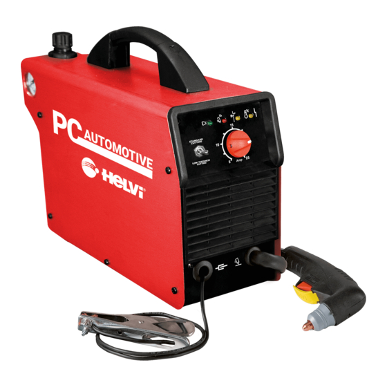
- Page 1 OPERATING MANUAL MANUALE D’ISTRUZIONE BEDIENUNGSANLEITUNG MANUEL D’INSTRUCTIONS MANUAL DE USO PLASMA CUTTING UNIT IMPIANTO DI TAGLIO AL PLASMA PLASMASCHNEIDGERÄT APPAREIL DE COUPAGE AU PLASMA EQUIPO DE CORTE POR PLASMA PC AUTO...
-
Page 2: Safety Rules And General Warnings
CAUTION! BEFORE INSTALLING, OPERATING OR CARRYING OUT MAINTENANCE ON THE PLASMA CUTTER, READ THE CONTENTS OF THIS MANUAL CAREFULLY, PAYING PARTICULAR ATTENTION TO THE SAFETY RULES. In the event of these instructions not being clear, please contact your supplier. CONGRATULATIONS ON YOUR NEW PURCHASE! YOU ARE NOW IN THE POSSESSION OF ONE OF THE SAFEST AND MOST TECHNOLOGICALLY ADVANCED PLASMA CUTTERS ON THE MARKET. - Page 3 CAUTION! Never, under any circumstances, look at an electric arc without eye protection. CAUTION! A further hazard for eyes is the risk of splinters or particles which may be detached during the cutting operations or during grinding, brushing or hammering away of the scale. Always wear goggles or protective shields with transparent lenses during these operations to prevent splinters or other foreign bo- dies from entering the eye.
-
Page 4: Power Supply Connection
Before installing the plasma cutting unit, carry out an inspection of the surrounding area, observing the following guidelines: 1 Make sure that there are no other power supply cables, control lines, telephone leads or other equipment near the unit. 2 Make sure that there are no radio receivers or television appliances. 3 Make sure there are no computers or other control systems. -
Page 5: Location And Handling Of The Power Source
LOCATION AND HANDLING OF THE POWER SOURCE √ Choose a location verifying that there is a good air flow and no dust, smoke or gas is present. √ Make sure that obstacles do not prevent the cooling air flow out of the front and rear openings of the machine. √ Arrange an open space of at least 5m around the machine. √ In the case the machine has to be moved, always disconnect the plug from the outlet and gather the cables and pipes so as not to damage them. COMPRESSED AIR A source of clean, dry air or nitrogen must be supplied to your plasma cutting unit. The supply pressu- re must be between 72.5 and 150 psi (5 and10.3 bar). -
Page 6: Cutting Operation
1. Green LED– Turns ON when input voltage is applied within normal range – blinks slowly when input voltage goes above 260Vac. 2. Red LED–Turns ON when torch is triggered. Blinks quickly during 1.5 second safety pre-flow prior to pilot arc ignition. Blinks slowly if cutting arcs not initiated after 1.5 second pilot arc ignition. 3. - Page 7 CUTTING A. CUTTING WITH A HAND TORCH √ The torch can be comfortably held in one hand or steadied with two hands. Choose the technique that feels most comfortable and allows good control and movement. Position the index finger or thumb to press the control switch on the torch handle. √ For edge starts, hold the torch perpendicular to the workpiece with the front of the tip on the edge of the workpiece at the point where the cut is to start. - Fig. A. For piercing, angle the torch slightly to direct sparks away from the torch until the pierce is complete.
-
Page 8: Torch Consumable Parts Selection
WARNING Disconnect primary power at the source and wait until the torch has cooled before disassembling the torch or torch leads. Frequently review the Important Safety Precautions at the front of this Manual. Be sure the operator is equipped with proper gloves, clothing, eye and ear protection. Make sure no part of the operator’s body comes into contact with the work piece while the torch is activated. -
Page 9: Operating Faults
OPERATING FAULTS During cutting operations performance faults may arise which are not caused by plant malfunctioning but by other operational faults such as: √ Insufficient penetration : too high cutting speed; torch is too tilted; piece is too thick; cutting current too low; torch parts are worn out;... - Page 10 TORCH Periodically, according to its use or to cutting faults verify wear of the parts connected to plasma arc: Shield Cup: Unscrew manually from head of the torch. Clean throughly and replace if damaged (burns, distortions or cracks). Verify integrity of superior metal sector (actuator torch safety). Tip: Check wear of plasma arc hole and of inner and outer surfaces.
-
Page 11: Trobleshooting
TROBLESHOOTING SYMPTOM POSSIBLE CAUSE AND REMEDY GREEN LED OFF, Fan not operating. 1. Plug unit into 240V outlet. No Input Power. 2. Reset Breaker. GREEN LED ON, YELLOW Overtemperature LED 1. Make sure the unit has not been operated ON. Unit is overheated. beyond duty cycle limits. - Page 12 ATTENZIONE “PRIMA DELL’INSTALLAZIONE, DELL’UTILIZZO O DI QUALSIASI MANUTENZIONE DELL’AP- PARECCHIO PER TAGLIO AL PLASMA, LEGGERE ATTENTAMENTE IL CONTENUTO DI QUE- STO MANUALE, PRESTANDO PARTICOLARE ATTENZIONE ALLE NORME DI SICUREZZA.” Nel caso queste istruzioni non Vi fossero chiare, non esitate a contattare il Vostro fornitore.
- Page 13 ATTENZIONE ! non guardare mai, in nessuna circostanza, un arco elettrico senza la protezione per gli occhi. ATTENZIONE ! Un ulteriore pericolo per gli occhi e’ rappresentato da schegge o corpu- scoli che si possono staccare durante le operazioni di taglio, molatura, spazzolatura o martellatura per la rimozione delle scorie.
-
Page 14: Collegamento Del Cavo Di Massa
Prima di installare il generatore di taglio al plasma eseguire una valutazione dell’area circostante se- guendo i punti guida qui elencati: 1-Verificare che non ci siano altri cavi di alimentazione, linee di controllo, cavi telefonici o sistemi in prossimita’ del generatore. 2-Verificare che non ci siano apparecchi ricevitori radio o tv. -
Page 15: Allacciamento Aria Compressa
UBICAZIONE E MOVIMENTAZIONE DELL ’UNITA’ Scegliere il luogo di ubicazione verificando che vi sia una buona circolazione di aria senza polveri, fumi o gas conduttivi o aggressivi. √ Assicurarsi che eventuali ostacoli non impediscano il flusso di aria di raffreddamento dalle aperture anteriori e posteriori della macchina. √ Prevedere uno spazio libero di almeno 5 m attorno alla macchina. √ Dovendo effettuare spostamenti della macchina staccare sempre la spina dalla presa di alimentazione e raccogliere tubi e tubazioni per evitare che possano essere danneggiati transitando sopra di essi. ALLACCIAMENTO ARIA COMPRESSA Predisporre una linea di distribuzione aria compressa pulita e secca o nitrogeno con le seguenti carat- teristiche minime:... -
Page 16: Operazioni Di Taglio
1 - Led verde - rimane acceso quando la tensione di linea è ok - lampeggia lentamente se la tensione di linea va sopra i 260Vac. 2 - Led rosso - si illumina quando la torcia è attivata. Lampeggia velocemente durante 1,5 secondi di pre-aria, prima dell’innesco dell’arco pilota. Lampeggia lentamente se l’arco di taglio non viene inne- scato dopo 1,5 secondi di arco pilota. 3 - Led giallo - Si accende quando la pressione è troppo bassa (sotto i 3.8 bar) 4 - Led giallo - Si accende quando interviene la Protezione Termica. 5 - Selettore Stardard Cutting / Spot Weld Removal 6 - Potenziometro regolazione corrente di taglio - Permette di impostare l’intensità della corrente di ta- glio fornita dalla macchina in conformità all’applicazione (spessore del materiale / velocità). - Page 17 TAGLIO A. TAGLIO CON TORCIA A MANO √ La torcia può essere tenuta confortevolmente in una mano o fermamente con due mani. Scegliere la tecnica più comoda e che permette un buon controllo e movimento. Posizionare il dito indice o il pollice per premere il pulsante di controllo sull’impugnatura della torcia. √ Per iniziare a tagliare dal bordo del pezzo tenere la torcia perpendicolare al pezzo con la parte fontale della punta sul bordo del pezzo nel punto in cui dovete iniziare a tagliare. FIG. A Per forare, inclinare leggermente la torcia per dirigire le scintille lontano dalla torcia finchè la foratura non è...
- Page 18 ATTENZIONE Scollegare il generatore dall’alimentazione prima di smontare la torcia o i suoi collegamenti. Riguardare frequentemente le Precauzioni di sicurezza all’inizio di questo manuale. Assicurarsi che l’operatore sia fornito di guanti, abbigliamento, protezioni per gli occhi e le orecchie idonei. Assicurarsi che nessuna parte del corpo dell’operatore venga in contatto con il pezzo mentre la torcia è attiva.
-
Page 19: Difetti Di Taglio
DIFETTI DI TAGLIO Durante le operazioni di taglio possono sorgere delle imperfezioni di prestazione che possono essere causate da malfunzionamenti di fabbrica o da altri difetti operativi come: √ Penetrazione insufficiente : velocità di taglio troppo elevata; torcia troppo inclinata; pezzo troppo spesso; corrente di taglio troppo bassa; parti della torcia consumate;... - Page 20 TORCIA Periodicamente, in funzione dell’intensità d’impiego o nell’evenienza di difetti di taglio, verificare lo stato d’usura delle parti della torcia interessate dall’arco plasma: Ugello: Svitare manualmente la testa della torcia. Eseguire un’accurata pulizia o sostituirlo se danneggiato (bruciature, deformazioni o incrinature. Verificare l’integrità del settore metallico superiore (attuatore sicurezza torcia). Cappa: Controllare l’usura del foro di passaggio dell’arco plasma e delle superfici interne ed esterne. Se il foro risulta allargato rispetto al diametro originale o deformato sostituire l’ugello.
-
Page 21: Ricerca Guasti
RICERCA GUASTI Indicatore di rete spento, ventilatore non lavora. 1. Collegare la macchina alla rete. 2. Ripristinare l’interruttore. Indicatore di rete ON, indicatore giallo di sovra- 1. L’unità è surriscaldata. Assicurarsi che la mac- temperatura ON. china non abbia lavorato oltri il limite del ciclo di lavoro. 2. - Page 22 ACHTUNG! VOR ANSCHLUSS, INBETRIEBNAHME ODER INSTANDHALTUNG DES PLASMASCHNEIDERS, LESEN SIE BITTE SORGFÄLTIG DIESE BETRIEBSANLEITUNG MIT BESONDERER BEACHTUNG DER SICHERHEITSHINWEISE. Sollten die Hinweise nicht klar sein, wenden Sie sich an Ihren Lieferanten. FOLGEN SIE UNSEREN HINWEISEN, WAS IHNEN EINE SICHERE UND PROBLEMLOSE ARBEIT MIT IHREM GERÄT GARANTIERT.
- Page 23 ACHTUNG! Unter keinen Umständen mit bloßem Auge in den Lichtbogen schauen! ACHTUNG! Eine weitere Gefahr für die Augen stellen umher fliegende Metalle – Splitter oder Teilchen dar, die beim Schneiden, dem Abkühlen oder Schleifen des Werkstückes auftreten können. Tragen Sie daher immer Eine geeignete Schutzbrille oder ein Schutzschild um Verletzungen an den Augen zu vermeiden.
-
Page 24: Allgemeine Informationen
Stellen sie vor der Inbetriebnahme sicher, dass sich in der näheren Umgebung des Plasmaschneid- gerätes: 1 - keine anderen Versorgungskabel, Kontrollleitungen, Telefonleitungen oder andere Anlagen befinden. 2 - keine Radioempfänger oder Fernsehapparate befinden. 3 - keine Computer oder andere Kontrollsysteme befinden. 4 - keine Personen mit Herzschrittmacher oder Hörgerät sind. - Page 25 √ Schalten sie vor jedem Transport den Netzschalter aus und ziehen den Netzstecker. Achten sie beim Transport darauf, dass keine Kabel beschädigt werden. DRUCKLUFTVERSORGUNG Für das Plasmaschneiden wird Druckluft benötigt. Bereiten Sie eine Versorgung mit sauberer und trocke- ner Druckluft oder Stickstoff mit den folgenden Eigenschaften: Luftdruck : 5-10.3 bar Durchfluss: 100L/min. (3.5 cu. ft./min) WICHTIG: Wenn Sie diesen Richtlinien nicht folgen, kann dies zur Überhitzung und Beschädi- gung des Brenners führen.
- Page 26 1. Grüne LED - schaltet ein, wenn das Gerät betriebsbereit ist. Wenn die Netzspannung 260V übersch- reitet, blinkt die langsam. 2. Rote LED – schaltet ein, wenn der Taster am Schneidbrenner betätigt wird. Vor dem Start des Pilot- lichtbogens blinkt die LED 1.5 Sekunden schnell. Wenn 1.5 Sekunden nach dem Start des Pilotbogens der Plasmalichtbogen nicht zustande bekommen ist blinkt die LED langsam und der Pilotlichtbogen verlöscht.
- Page 27 SCHNEIDEN SCHNEIDEN MIT DEM SCHNEIDBRENNER √ Der Schneidbrenner kann komfortabel mit einer Hand oder beiden Händen gehalten werden. Wählen Sie die Handhabung, die für Sie am bequemsten ist und Ihnen eine gute Kontrolle und Bewe- gungsfreiheit ermöglicht. Legen Sie den Zeigefinger oder den Daumen so, dass Sie den Brennertaster auf dem Brennergriff drücken können.
- Page 28 C. SPOT WELD REMOVAL √ Um die Schweißpunkte zu entfernen oder um sehr geringen Strömen zu schneiden, stellen Sie “Spot Weld Removal” mit dem Wahlschalter (5) auf der Vorderseite der Maschine. Man reduziert die Luftströmung und verhindert, dass der Schneidlichtbogen leicht erlischt. √ Benutzen Sie die 2-Loch Schutzhaube (markiert mit “compressor”) und die ø 0,65 mm Schneiddüse. √ Starten Sie an der Stelle neben schneiden zu entfernen und bewegen sich sehr schnell um ihn herum. D. SCHNEIDEN VON GITTERPLATTEN Zum Schneiden von Gitterplatten stellen Sie den Schneidstrom zwischen 20 und 25A. WARNUNG Schalten sie die Stromquelle aus und warten sie bis sich der Schneidbrenner abgekühlt hat, bevor Sie Arbeiten an diesem (z.B.
- Page 29 BEDIENUNGSFEHLER Beim Schneiden können Fehler auftreten, die nicht durch einen Defekt der Anlage, sondern durch Bedie- nungsfehler verursacht werden, wie: Ungenügende Eindringtiefe : zu hohe Schneidgeschwindigkeit; die Schneidbrenner ist zu stark geneigt; das Werkstück ist zu dick; der Schneidestrom ist zu gering; die Verschleißteile sind verschlissen;...
- Page 30 SCHNEIDBRENNER Überprüfen sie regelmäßig, je nach Benutzung oder Auftreten von Schneidefehlern den Verschleiß der Elektrode, der Schneiddüse und der Schutzkappe: Schutzhaube: Schrauben Sie die Schutzkappe manuell vom Brennerkopf ab. Reinigen Sie sie gründlich oder, falls be- schädigt (Anbrennungen, Verformungen oder Risse), wechseln sie sie. Prüfen Sie auch die Aufnahme der Schutzkappe am Brennerkopf (Schutzschalter für die Brennersicherheit). Schneiddüse: Prüfen Sie den Verschleiß der Bohrung sowie der inneren und äußeren Oberflächen. Sollte die Öffnung im Verhältnis zu ihrer ursprünglichen Weite sein, wechseln Sie die Düse.
- Page 31 HINWEISE ZUR FEHLERBEHANDLUNG A. GRÜNE LED leuchtet nicht, der Lüfter arbeitet 1. Gerät mit dem Netz verbinden. nicht. Keine Netzspannung. 2. Den Leistungsschalter zurücksetzen B. GRÜNE LED leuchtet, GELBE LED Übertempe- 1. Die Einschaltdauer des Gerätes wurde über- ratur leuchtet. Das Gerät ist überhitzt. schritten. Gerät abkühlen lassen. 2.
- Page 32 ATTENTION “AVANT D’INSTALLER, D’UTILISER OU D’EFFECTUER N’IMPORTE QUEL ENTRETIEN SUR L’APPAREIL DE DÉCOUPAGE AU PLASMA, IL FAUT LIRE ATTENTIVEMENT LE CONTENU DE CE MANUEL, EN FAISANT PARTICULIÈREMENT ATTENTION AUX NORMES DE SÉCURITÉ” Si ces instructions n’étaient pas claires, n’hésitez pas à contacter votre fournisseur” NOUS VOUS FÉLICITONS POUR VOTRE ACHAT! VOUS POSSÉDEZ MAINTENANT UN DES APPAREILS POUR LE DÉCOUPAGE AU PLASMA LES PLUS SÛRS ET TECHNOLOGIQUEMENT AVANCÉS.
- Page 33 4-Chaussures de protection 5-Masque de protection (mieux encore un casque) suffisamment ample à protéger tout le visage et doté de vitres de protection en mesure de filtrer toutes les radiations et de réduire au minimum l’intensité lumineuse absorbée par les yeux. ATTENTION! Ne jamais regarder, pour aucune raison, un arc électrique sans une protection pour les yeux. ATTENTION! Un autre danger pour les yeux est représenté...
-
Page 34: Branchement Du Cable De Masse
ATTENTION! Éviter de diriger le jet de la torche contre des personnes ou des corps étrangers. Avant d’installer le générateur de découpage au plasma, effectuer une évaluation de la zone environ- nante selon les points suivants: 1- Vérifier qu’il n’y ait pas d’autres câbles d’alimentation, lignes de contrôle, câbles téléphoniques ou systèmes à proximité du générateur. -
Page 35: Branchement De L 'Air Comprimé
SITUATION ET DÉPLACEMENT DE LA SOURCE DE COURANT Choisir l’emplacement en vérifiant qu’il y ait une bonne circulation d’airexempte de poussières, fumées ou gaz conducteurs ou agressif. S’assurer qu’aucun obstacle n’empêche le passage d’air de refroidissement par les ouvertures avant et arrière de la machine. Prévoir un espace libre d’au moins 500mm autour de la machine. En cas de nécessité... - Page 36 Voyant LED vert - S’ALLUME lorsque la tension d’entrée est appliquée dans un registre normal. Clignote lentement lorsque la tension d’entrée dépasse 260 VAC. Voyant LED rouge - S’ALLUME lorsque la torche est activée. Clignote rapidement pendant le pré -écoulement de sécurité de 1.5 secondes avant le démarrage de l’arc pilote. Clignote lentement si l’arc coupant n’est pas amorcé...
- Page 37 COUPE A. DÉCOUPE AVEC LE CHALUMEAU À MAIN √ Le chalumeau peut être confortablement tenu à une main, ou plus fermement avec les deux mains. Choisissez la technique avec laquelle vous vous sentez le mieux et qui vous permet un bon contrôle du mouvement. Positionnez votre index ou votre pouce pour appuyer sur le commutateur de com- mande de la poignée du chalumeau.
- Page 38 AVERTISSEMENT Débranchez la source d’alimentation secteur avant de procéder au démontage du chalumeau ou de ses câbles. Relisez fréquemment les précautions de sécurité importantes du début de ce manuel. Assurez- vous que l’opérateur est bien équipé avec gants, vêtements et protections oculaire et auditive appro- priées. Assurez-vous qu’aucune partie du corps de l’opérateur n’entre en contact avec la pièce de travail lorsque le chalumeau est activé.
-
Page 39: Disfonctionnements Habituels
DISFONCTIONNEMENTS HABITUELS Voici une liste des problèmes de découpe fréquents avec leurs causes possibles : √ Pénétration insuffisante: Vitesse de découpe trop rapide Chalumeau trop incliné Métal trop épais Pièces de chalumeau usées Courant de coupe insuffisant Pièces n’étant pas d’origine √ Extinction de l’arc principal: Vitesse de découpe trop lente Courant de découpe trop bas, régler “Spot Weld Removal» Écartement du chalumeau trop important par rapport à la pièce Alimentation CA trop faible, courant de sortie réduit Câble de masse sur la pièce débranchée Pièces de chalumeau usées Pièces n’étant pas d’origine... - Page 40 TORCHE Périodiquement, en fonction de l’intensité d’utilisation ou en cas de défauts de coupe, vérifier l’état d’u- sure des parties de la torche intéressées par l’arc plasma: Porte-buse: Dévisser manuellement la tête de la torche. En effectuer soigneusement le nettoyage et le remplacer s’il est endommagé...
-
Page 41: Dépannage
DÉPANNAGE A. Indicateur de CA éteint, le ventilateur ne fon- 1. Rancher l’unité dans une prise de 230V. ctionne pas. Pas de Puissance d’entrée. 2. Le disjoncteur général en amont a déclenché. Rétablir le Disjoncteur. B. Indicateur de CA allumé, indicateur de sur- 1. Vérifier que l’unité n’ait pas fonctionné au-delà... - Page 42 ¡ATENCIÓN! “ANTES DE LA INSTALACIÓN, DE LA UTILIZACIÓN O DE CUALQUIER MANTENIMIENTO DEL EQUIPO DE CORTE AL PLASMA, LÉASE ATENTAMENTE EL CONTENIDO DE ESTE MA- NUAL, PRESTANDO ESPECIAL ATENCIÓN A LAS NORMAS DE SEGURIDAD.” Si estas instrucciones no le fueran claras, no dude en consultar a su proveedor. ¡LE FELICITAMOS POR SU COMPRA! AHORA POSEE UNO DE LOS EQUIPOS DE CORTE AL PLASMA MÁS SEGUROS Y TECNOLÓGICAMENTE AVANZADOS.
- Page 43 ¡ATENCIÓN! Jamás y bajo ninguna circustancia mire un arco eléctrico sin la protección para los ojos. ¡ATENCIÓN! Oltro peligro para los ojos está representado por las astillas o partículas que pueden saltar durante el corte, esmerilado, cepil- lado o martillado para la eliminación de escorias. Durante dichas operaciones póngase siempre las gafas o pantallas de protección con cristales transparentes para impedir que entren en los ojos las astillas u otros cuerpos extraños.
-
Page 44: Conexion Al Cable De Tierra
Antes de instalar el equipo de corte por plasma, controle el área circunstante, siguiendo los puntos que, como guía, se indican a continuación: 1- Verifique que no haya otros cables de alimentación, líneas de control, cables telefónicos u otros equi- pos en proximidad del equipo. -
Page 45: Conexion Del Aire Comprimido
LOCALIZACION Y MANIPULACION DE LA FUENTE DE CORRIENTE Elegir el lugar, comprobando que haya buena ventilación, sin polvo, humo o gas conductivos o agre- sivos. Asegurarse que no haya obstáculos que eviten la salida del flujo de aire fresco, de las aperturas frontales y posteriores de la máquina. -
Page 46: Operaciones De Corte
1. LED Verde - Se ENCIENDE cuando el voltaje de entrada se aplica dentro del rango normal. Parpa- dea lentamente cuando el voltaje de entrada excede 260Vac. 2. LED Rojo - Se ENCIENDE cuando la antorcha se activa. Parpadea rápidamente durante el preflujo de seguridad de 1.5 segundos antes del inicio del arco piloto. - Page 47 CORTE A. CORTE CON ANTORCHA MANUAL √ La antorcha puede manejarse confortablemente con una mano o con dos manos. Elegir la técnica más cómoda y que permita un buen control del movimiento. Posicionar el índice o el pulgar para apretar el pulsador de la antorcha. √ Para empezar el corte desde el borde de la pieza mantener la antorcha perpendicularmente con la pieza, la punta de la antorcha debe colocarse en el borde de la pieza, allí donde empezará el corte. (Fig.
- Page 48 ATENCIÓN Desconectar el generador de alimentación antes de desmontar la antorcha o sus conexiónes. Repasar frecuentemente las “Precauciónes de seguridad” al principio de este manual. Asegúrese que el operador lleve guantes, ropas, protecciónes para los ojos y las orejas idóneas. Asegúrese que ninguna parte del cuerpo del operador venga en contacto con la pieza mientras que la antorcha está...
-
Page 49: Errores De Corte Mas Comunes
ERRORES DE CORTE MAS COMUNES Durante la realización de operaciónes de corte, pueden surgir inconvenientes que non son causados por mal funcionamiento del equipo o por otros aspectos operativos, tales como: √ Penetración insuficiente: velocidad de corte demasiado alta; la antorcha està demasiado inclinada; la pieza es demasiado espesa; la corriente de corte es demasiado baja;... - Page 50 ANTORCHA Periódicamente, de acuerdo a su uso o a errores de corte, comprobar el desgaste de piezas conectadas al arco plasma: Asa de la boquilla: Desenroscar manualmente de la cabeza de la antorcha. Limpiar totalmente y sustituirla si está dañada (quemada, torcida o rota).
-
Page 51: Busqueda De Averias
BUSQUEDA DE AVERIAS A. Indicador de la presencia de la red apagado, 1. Enchufe la unidad a una salida de 230V. ventilador no funciona 2. Interruptor abierto. Restablezca el interruptor. B. Indicador de red encendido, indicador amarillo 1.La unidad está sobrecalientada. Asegúrese que de sobrecalientamiento encendido. - Page 52 TORCH PARTS LIST AND EXPLODED VIEW TORCH HEAD ELECTRODE AIR DIFFUSER TIP D.0,8 (15-25A) TIP D. 0,65 (5-15A) SHIELD CUP “06” SHIELD CUP “COMPRESSOR” ELECTRODE WRENCH HANDLE+MICRO CABLE ASSEMBLY SPACER UNIT PARTS LIST AND EXPLODED VIEW MANUAL/AUTOMATIC SWITCH PLASTIC ABAT-VENT L=140 RED KNOB D.26 FOR POTENTIOM. + POINTER FRONT FRAME CONTROL PCB STM8 PL30 HALF BRIDGE 230V...
-
Page 54: Wiring Diagram
WIRING DIAGRAM... - Page 55 SMALTIMENTO DI APPARECCHI DA ROTTAMARE DA PARTE DI PRIVATI NELL’UNIONE EUROPEA Questo simbolo che appare sul prodotto o sulla confezione indica che il prodotto non deve essere smaltito assieme agli altri rifiuti domesti- ci. Gli utenti devono provvedere allo smaltimento delle apparecchiature da rottamare portandole al luogo di raccolta indicato per il riciclag- gio delle apparecchiature elettriche ed elettroniche.
- Page 56 77611881...
Need help?
Do you have a question about the PC AUTO and is the answer not in the manual?
Questions and answers