Table of Contents
Advertisement
Quick Links
Advertisement
Table of Contents

Related Manuals for ATS 2330 Series


Summary of Contents for ATS 2330 Series
- Page 1 INSTRUCTION MANUAL PLC Lever Arm Tester This manual contains important operating and safety information. Carefully read and understand the contents of this manual prior to the operation of this equipment. www.atspa.com MAN - PLC Lever Arm Tester - REV: 01...
- Page 2 Information in this document is subject to change without notice and does not represent a commitment on the part of Applied Test Systems (ATS). © Copyright Applied Test Systems 2019 For assistance with set-up or operation, contact the ATS service department. Please have this manual and product serial number available when you call. Telephone: +1-724-283-1212...
-
Page 3: Table Of Contents
Manual Contents A. Introduction ........................1 A.1 Unpacking ..............................1 A.2 After Sale Support ............................1 B. Safety ..........................2 B.1 For Owners, Operators, and Maintenance ....................2 B.2 Cautions ...............................3 C. System Overview ......................4 C.1 Safety Label Locations ..........................4 C.2 Equipment Parts ............................6 C.3 General Description .............................7 Product Specifications ...........................7 D. - Page 4 Unload at End of Test ........................... 13 IP Address ............................13 Current Time ............................13 Start Delay ............................13 Done Button ............................13 F. Operation ........................14 F.1 Basic Operation ............................14 F.2 Sample Break ............................. 15 G. Maintenance ........................16 G.1 Knife Edges ...............................16 G.2 V-Blocks ..............................
-
Page 5: Introduction
Retain all cartons and packing materials until the unit is operated and found to be in good condition. If damage has occurred during shipping, notify Applied Test Systems (ATS) and the carrier immediately. If it is necessary to fi le a damage claim, retain the packing materials for inspection by the carrier. -
Page 6: Safety
All ATS equipment is designed to be operated with the highest level of safety. To maintain the safe operation of this tester, ATS endeavors to educate the operator about safety issues surrounding certain parts of the machinery. -
Page 7: Cautions
CAUTION: Read and follow all WARNING and CAUTION statements in all related equipment manuals before attempting to operate this machine. If in any doubt about any statement or sentence, contact the ATS Service Department or your ATS Sales Engineer. CAUTION: Installation of electrical devices must be accomplished by competent personnel and done in accordance with any current local and national codes. -
Page 8: System Overview
C. System Overview C.1 Safety Label Locations Figure C.1: Safety Label Location, Side MAN - PLC Lever Arm Tester - REV: 01 | C. System Overview... - Page 9 Figure C.2: Safety Label Location, Front MAN - PLC Lever Arm Tester - REV: 01 | C. System Overview...
-
Page 10: Equipment Parts
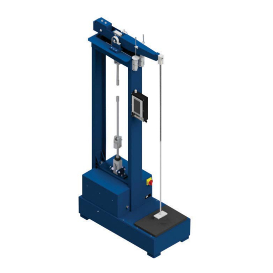
C.2 Equipment Parts 1. Frame 2. Lever Arm 3. Knife Edge Support Block 4. Safety Guard 5. Weight Pan Shackle 6. Roller Chain 7. Auto Leveling Actuator 8. Auto Leveling Sensor 9. Weight Pan 10. Isolator Pads 11. Shock Pad 12. -
Page 11: General Description
C.3 General Description The ATS lever arm testers have evolved to include the following design features: • Open frame construction, aids in placement of accessory equipment to suit individual testing needs. • Lever arm knife edges provide the contact fulcrum for the arm. Knife edges are rotatable with four edges and are easily replaceable to maintain accuracy. -
Page 12: Installation
D. Installation D.1 Unpack and Set Up 1. Carefully remove the shipping crate and packing materials from the tester. Do not discard the packing materials until all items on the invoice have been accounted for. 2. Use an overhead crane or forklift to remove the test frame and control console from the pallet and position it in the desired location. - Page 13 Counterweight Counterweight V- Blocks Positioning Locking Screw Screw Counterweight Safety Guards (Between Side Plates) Auto-Leveling Knife Edge Actuator Figure D.1: Lever Arm Assembly (Dual Ratio Shown) 5. Install the lever arm onto the tester with the V-blocks mated to the knife-edges. Be careful not to damage knife-edges or v-blocks.
-
Page 14: Software Overview
E. Software Overview E.1 Main Screen Figure E.1 below shows the Main Screen. This is shown when the PLC Lever Arm is started. It allows you to setup and run machine cycles. Figure E.1: Main Screen Figure E.2: Main Screen, Cycle State Process Time Will only be displayed if a timed test type is selected. -
Page 15: End/Stop Button
“Remaining Time” being displayed. This will show up for the “Running”, “Unload”, and “Delay Start” states and will display the time remaining for that part of the cycle. If an indefinite test is selected, “Elapsed TIme” will be displayed. End/Stop Button Used to tell the system to finish the cycle. -
Page 16: Test Complete State
The screen will show the current version of the software in the PLC and HMI. This is very important information, and is most often ask for when calling into ATS service. MAN - PLC Lever Arm Tester - REV: 01 | E. Software Overview... -
Page 17: Test Type
Figure E.9: View Screen Test Type Used to select what type of test to run. The “Timed Test” will run until a time period is finished. The “Indefinite Test” will run until the specimen breaks or the operator stops the test. Unload at End of Test This checkbox tells the system to unload the sample at the end of a test. -
Page 18: Operation
F. Operation F.1 Basic Operation 1. Adjust Level Sensor Actuator so sensor is just off when the arm is level. 2. Adjust the Break Sensor Pan so that the sensor is just on when the weights are sitting on the weight pad. 3. -
Page 19: Sample Break
F.2 Sample Break If during the test cycle a sample breaks you have two options. 1. Press the “End/Stop” to abort the test where it is. 2. Continue the test: a) Take the broken sample out of the load train. b) Reconnect the load train. -
Page 20: Maintenance
G. Maintenance G.1 Knife Edges Check quarterly or after heavy loading. If damaged, rotate to a new edge. Replace when all four edges have been used. Lever arm must be recalibrated once knife edge is rotated or replaced. G.2 V-Blocks Regrind or replace if damaged. -
Page 21: Appendix A: Warranty
Appendix A: Warranty Your Applied Test Systems product has been manufactured and inspected by experienced craftsmen. Applied Test Systems warrants, for the original purchaser, each product to be free from defects in material and workmanship for a period of thirteen (13) months from date of shipment or twelve (12) months from date of installation - whichever comes first. -
Page 22: Appendix B: Wiring Diagram
Appendix B: Wiring Diagram BLU_#16AWG BRN_#16AWG BLK_#20AWG INPUT OUTPUT DC 3A BLK_#20AWG WHT_#20AWG BLK_#20AWG LINE FILTER BLK_#20AWG U:\Eng Drawing Files\2-XXXX\2-95XX\2-9546-R0-S1.DWG CAD DWG FILE DATE REVISION MAN - PLC Lever Arm Tester - REV: 01 | Appendix B: Wiring Diagrams... - Page 23 RED_#22AWG BLK_#22AWG BRN_#22AWG RED_#22AWG WHT_#20AWG RED_#20AWG BLK_#22AWG JUMPERBAR JUMPERBAR JUMPERBAR JUMPERBAR JUMPERBAR U:\Eng Drawing Files\2-xxxx\2-95xx\2-9546-R0-S2.DWG CAD DWG FILE DATE REVISION MAN - PLC Lever Arm Tester - REV: 01 Appendix B: Wiring Diagrams...
-
Page 24: Appendix C: Image Glossary
Appendix C: Image Glossary Figure A.1: ATS Sample Data Tag..........................1 Figure C.1: Safety Label Location, Side .........................4 Figure C.2: Safety Label Location, Front ........................5 Figure C.3: Basic Lever Arm Front ..........................6 Figure D.1: Lever Arm Assembly (Dual Ratio Shown)....................9 Figure E.1: Main Screen ...............................10 Figure E.2: Main Screen, Cycle State ..........................10...
Need help?
Do you have a question about the 2330 Series and is the answer not in the manual?
Questions and answers