Table of Contents
Advertisement
Quick Links
Advertisement
Table of Contents

Related Manuals for ATS 530 Series


Summary of Contents for ATS 530 Series
-
Page 1: Instruction Manual
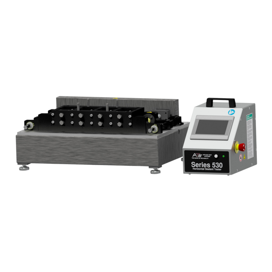
INSTRUCTION MANUAL Series 530 Horizontal Sealant Tester This manual contains important operating and safety information. Carefully read and understand the contents of this manual prior to the operation of this equipment. www.atspa.com MAN - Series 530 Horizontal Sealant Tester - REV: 02... - Page 2 Information in this document is subject to change without notice and does not represent a commitment on the part of Applied Test Systems (ATS). © Copyright Applied Test Systems 2018 For assistance with set-up or operation, contact the ATS service department. Please have this manual and product serial number available when you call. Telephone: +1-724-283-1212.
-
Page 3: Table Of Contents
Manual Contents A. Introduction ...........................1 A.1 Unpacking ..............................1 A.2 Warranty Information .............................1 A.3 After-Sale Support ............................1 B. Safety .............................2 B.1 For Owners, Operators, and Maintenance ....................2 B.2 Safety Instructions ............................2 B.3 Cautions ................................3 B.4 Warnings................................3 C. System Overview ..........................4 C.1 General Product Description .........................4 C.2 Product Specifications ..........................4 D. - Page 4 E.6 Program Log Screen ...........................15 Cyclic Count Field ..........................16 Goto Count Field ...........................16 Elapsed Time Field ..........................16 Delete All Log Data Button ........................17 Backup All to USB Button ........................17 Month, Day, Year, Hour, Minute, and Second Fields ................17 Done Button ............................17 E.7 New HMI Software ............................17 F.
-
Page 5: Introduction
Retain all cartons and packing materials until the unit is operated and found to be in good condition. If damage has occurred during shipping, notify Applied Test Systems (ATS) and the carrier immediately. If it is necessary to file a damage claim, retain the packing materials for inspection by the carrier. -
Page 6: Safety
B. Safety B.1 For Owners, Operators, and Maintenance All ATS equipment is designed to be operated with the highest level of safety. This manual uses note, caution, and warning symbols throughout to draw your attention to important operational and safety information. -
Page 7: Cautions
B.3 Cautions The following statements are CAUTION statements. These statements alert the operator to conditions that may damage equipment. Operators must be aware of these conditions in order to ensure safe operation of the equipment. CAUTION: Installation of electrical device must be accomplished by qualified personnel and done in accordance with any current local and national codes. -
Page 8: System Overview
C. System Overview C.1 General Product Description Applied Test System’s Series 530 Horizontal Sealant Testers are used to perform cyclic tension/compression tests on joint sealing compounds. This tester may be used alone or with a refrigeration unit for testing at lower temperatures. -
Page 9: Installation
3. Connect the cable between the testing machine and control cabinet. The distance between the control cabinet and tester is limited by the length of the control cable. Additional cables can be obtained by contacting ATS. 4. If necessary for testing, connect the temperature controller and the optional freezer unit, as described in Section D.2. - Page 10 3. In the IP Address Field, enter the IP Address of the Ethernet port on the back of the Series 530 Horizontal Sealant Tester control box. 3. Using any downloaded VNC Viewer program, users can now login to view their equipment remotely. MAN - Series 530 Horizontal Sealant Tester - REV: 02 | D.
-
Page 11: Software Overview
E. Software Overview E.1 Software Map Figure E.1 illustrates the proper navigation of the Series 530 Sealant Tester’s software screens. 540 Menu Flow Main Screen Only with Temp Option Drive Enable/Disable Jog Speed Temp Setpoint Only when not in cycle Only wh en not in cycle Only with Temp Option Start Cycle... -
Page 12: Main Screen
E.2 Main Screen Figure E.2 illustrates the Main Screen that is displayed when the machine is started. It allows you to setup, and run, tests. The screen will show machine Displacement. It also has several controls to set-up and run the machine. Figure E.2: Main Screen The following buttons are located on the Main Screen: Zero Button... - Page 13 Jog Open and Close Buttons Will jog the machine in the desired direction at the currently selected jog speed. Return Xhead Button Send the crosshead back to the zero displacement position at the current jog speed if the drive system is enabled.
- Page 14 Temperature Units Allow the system temperature to show and be programed in English (°F) or Metric (°C) units. This will only be displayed if the system has a temperature control option and is not running a test. Current Temp Displays the current chamber temperature. This will only be displayed if the system has a temperature control option.
-
Page 15: Alarm Screen
Speed Display Displays the last commanded speed of the system. Step # Field Displays the step number of the program that is currently being executed. Count Fields Only show up if the current program step is a “Cycle Position” move. The gray field is the total number of cycles programed. -
Page 16: Language Screen
will not go away until a power cycle. The “Done” button will return you to the previous screen. E.4 Language Screen Figure E.6 illustrates the Language Screen. It is shown anytime the “Language” button is pressed on the Configure Screen. Figure E.5: Language Screen To change the language the system is using, simply press the flag of the language you wish to use. -
Page 17: New Program Button
Figure E. 9 shows the “Program” screen. It appears anytime the “Program” button is pressed on the main screen. Its main purpose is to display, edit, save, and load the program in the machine. NOTE: There are 10,000 steps possible for each program. Most programs will have less than 20. -
Page 18: Program Steps Data Section
Goto Step Has a step number and count entry. The step number must be a previous step. This is a loop control. The program will jump back to the entered step and execute the program from there to the goto for count times. Then it will move on to the next step of the program. -
Page 19: Do Not Turn Off Temperature At End Of Program
Do Not Turn off Temperature at End of Program May be checked if you have many samples to run and wish the chamber to stay at temperature. Otherwise the control system will shut down at the end of a test. This will only be displayed if the system has the temperature control option. -
Page 20: Cyclic Count Field
The next field is the program step number. The next field is the program function for that step. The following is a list of these functions. Program function numbers: No Operation Move to Position Wait for position Cyclic Position Goto Step Hold Set Temperature Wait for Temperature... -
Page 21: Delete All Log Data Button
The field to the top right of the screen is used to select the program log file to display. The log file name is date and time it was created. Delete All Log Data Button Asks you to confirm that you wish to delete all log files on the HMI. If you answer yes then all log data on the HMI will be deleted. - Page 22 The necessary files will now be downloaded. Figure E.10: Subdirectories When done, remove the flash drive and replace the USB port cap. MAN - Series 530 Horizontal Sealant Tester - REV: 02 | E. Software Overview...
-
Page 23: Operation
F. Operation F.1 Test Frame The test frame is constructed with twin ball screws driven by an electronically controlled servo motor driving the loading crosshead. Fixed stops on the limit switch actuator rod are set at the factory to protect the test frame by limiting crosshead movement. - Page 24 2. Attach the specimen bracket (Item 1, Figure F.1) to the crossheads. 3. Affix brackets to crossheads using bolts and lock washers (Item 2, Figure F.1) on both sides. 4. Operate as described in Section F.2. Figure F.1 - Roofing Fixture MAN - Series 530 Horizontal Sealant Tester - REV: 02 | F.
-
Page 25: Troubleshooting
Additionally, some errors may need the system to be power cycled to reset them. If you have trouble resetting an error or would like more information about an error please contact the Applied Test Systems (ATS) Service Department at +1-724-283-1212. - Page 26 2. Using a 1/8” Alley Key or T-Handle, remove (5) #10-32 bolts located in front and back of the Pulley Guard. There are three on the front, and two on the back. Figure G.3, Figure G.4 - Bolts in front and back of Pulley Guard 3.
- Page 27 5. Lift up on the Drive Assembly and remove the belt from the upper pulleys. Figure G.8 - Remove belt 6. Use a 5/16” Allen Key T-Handle wrench to remove the 3/8”-16 bolts that hold down the sealant specimen fixture to the crossheads.
- Page 28 8. To adjust pulleys, turn both counterclockwise until they evenly press up against the gage blocks. Ensure there is no binding, which may cause misalignment. Figure G.11 - Adjust pulleys 9. Once evenly aligned, reattach belts, apply downward pressure on the drive mounting plate (shown in Figure G.12), and re-tighten the 4 bolts.
-
Page 29: Maintenance
H. Maintenance H.1 Checking Belt Tension Belt tension should be checked at every calibration (or if movable crosshead is not moving). If the belt is loose, the bolts holding the motor mounting plate will need to be loosened (see Figure H.1), belts re-tensioned (motor plate slid down to apply belt tension), and bolts re-tightened. -
Page 30: Appendix A: Warranty
Appendix A: Warranty Your Applied Test Systems product has been manufactured and inspected by experienced craftsmen. Applied Test Systems warrants, for the original purchaser, each product to be free from defects in material and workmanship for a period of thirteen (13) months from date of shipment or twelve (12) months from date of installation - whichever comes first. -
Page 31: Appendix B: Image Glossary
Appendix B: Image Glossary Figure A.1 - ATS Sample Data Tag ..........................1 Figure E.1: Series 530 Sealant Tester Software Map ....................7 Figure E.2: Main Screen ..............................8 Figure E.3 - Main Screen, Test Running ........................10 Figure E.4: Alarm Screen .............................. 11 Figure E.5: Language Screen ............................12...
Need help?
Do you have a question about the 530 Series and is the answer not in the manual?
Questions and answers