Advertisement
Quick Links
Advertisement

Subscribe to Our Youtube Channel
Related Manuals for Modena BZ 1014


Summary of Contents for Modena BZ 1014
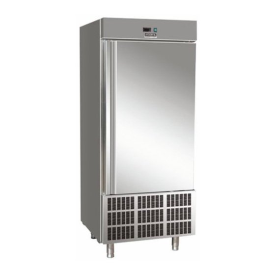
- Page 1 User Manual Book Blast Chiller BZ 1014, BZ 1010, BZ 1005...
- Page 2 Thank you for your trust in choosing MODENA products for your household needs. With your satisfaction as our priority, we constantly aim to deliver stylishly designed products equipped with state-of-the-art technology to assist you in your daily activities. This is your guidebook containing everything you need to know about our product. Please reach out to us if you need further assistance or other information via our Customer Care or our official website www.modena.com.
-
Page 3: Table Of Contents
CONTENTS Hal. INTRODUCTION Part 1 : Regulation & General Instruction Part 2 : Name of Parts Part 3 : Installation Part 4 : How to Use Part 5 : Cleaning & Maintenance Part 6 : Troubleshooting Part 7 : Disposal Part 8 : Refrigerant Technical Card Part 9... - Page 4 Part 1: Regulation & General Instruction A. General Information This manual book is designed by the manufacturer to provide the necessary information to those who are authorized to interact with the appliance. The persons receiving the information must read it carefully and apply it strictly. Reading the information contained in this document will allow the user to prevent risks to personal health and safety.
-
Page 5: Part 3: Installation
Pull the cardboard packaging upwards. After unpacking the appliance, ensure the features correspond with the requested ones on the order. Contact MODENA Call Center immediately if any a incompatibility occurs. Packaging elements (nylon bags, polystyrene foam, staples ) must be kept away from children. - Page 6 Remove the protective PVC film from the internal and external walls, avoiding the use of metal tools. B. Installation All the installation phases must be considered from the general plan. The installation area must be equipped with all power supply and production residue drainage connections and must comply with local regulations regarding the hygiene and sanitary requirements.
- Page 7 Part 4: How to Use Safety It is recommended to carefully read the instructions and warnings in this manual book before operating the appliance. The information in the manual book is fundamental for the safety of the use and for maintenance. Keep this manual carefully.
- Page 8 indirect contact with the foodstuffs must be cleaned very well along with the surrounding areas . These operations must only be performed using detergents that can be used with foodstuffs, avoiding inflammable products or those that contain substances that are harmful to personal health. In the case of prolonged inactivity, as well as disconnecting all the supply lines, it is necessary to accurately clean all internal and external parts of the appliance.
- Page 9 The chiller should be used for storage for short periods only. To prevent bacterial contamination or contamination of any other biological nature, the needle probe must be disinfected after use. To extract the product that has undergone blast chilling or shock freezing ,always wear gloves to protect the hands.
- Page 10 Installation Model XB570L is a controller panel attached to the appliance; with the hole diameter of 150x31 mm, and screwed in. The ambient operating temperature range is 0÷60°C. Avoid locations with heavy vibration, corrosive gases or excessive dirt. The same applies to the probes. Ensure ventilation around the appliance. Electrical connections The instruments are provided with a screw terminal block to connect cables with a cross section up to 2.5mm²...
- Page 11 Display Temperature. Timer or insert probe. Alarm and status icons. If an icon or LED is on, the correspondent function is enabled. If an icon or LED is flashing, the correspondent function is delayed. Buttonboard in stand-by ...
- Page 12 How display/modify the set. Point if the holding phase to display: Push and release the (6) SET button, the holding set point of the selected cycle is displayed for 5 seconds. To modify: while the set point is displayed hold pushed the SET button till the HdS label start flashing.
- Page 13 - iSI = Stop phase set point, referred to the insert probe - Back to the room temperature. How to modify the room set point While rSI or iSI are displayed hold pushed the SET button till the rSi or iSi label start flashing and LED near the SET button is turned on.
- Page 14 Light (4): push the LIGHT (4) button to switch the light on and off. The status of the light is monitored by the yellow LED upper the button. AUX (8): push the AUX (8) button to switch the auxiliary on and off. The status of the auxiliary relay is monitored by the yellow LED upper the button.
- Page 15 Meaning of the LEDS’ A series of light points on the front panels is used to monitor the loads controlled by the instrument. Each LED function is described in the following table. How to select a cycle Push the to move among the cycles C1, C2, C3, C4 and the holding cycle.
- Page 16 cut IN is Set Point Plus Differential (Hy). Compressor cut OUT is when the temperature reaches the set point. - AC Anti-short cycle delay: (0÷30 min) minimum interval between the compressor stop and the following restart. - PAU Time of stand by: (0 ÷ 60min) after this time the controller restart the cycle. - PFt Maximum acceptable duration of power failure: (0 ÷...
- Page 17 open alarm is signaled.; n = compressor and fans stay according to the odc parameter when door open alarm is signaled. - d2F(EAL, bAL,) Second digital input configuration (26-27): EAL: external alarm; bAL: serious alarm, regulation is stopped.; - d2P: Configurable digital input polarity (26-27): (OP÷CL)select if the digital input is activated by opening or closing the contact.
- Page 18 Auxiliary relay management OSt AUX output timer: (0÷255 min) time in which the AUX output stays ON. It is used when oA1 or oA2 or oA3 = tMr. With oAt = 0 the AUX relay is switched on and off only manually. OSS Set point for AUX output, used when oA1 or oA2 or oA3 = AUS (-50÷50;...
- Page 19 ALL Minimum temperature alarm (it is used only during the holding phase): (1÷50°C/1°F) When the “SET-ALL” temperature is reached the alarm is enabled, (possibly after the “ALd” delay time). ALd Temperature alarm delay (it is used only during the holding phase): (0÷255 min) time interval between the detection of an alarm condition and alarm signaling.
- Page 20 rS2 (-50÷50°C; 1°C/1°F) Room probe Set point for the second phase: it prevents temperature from reaching a too low value during the second phase. Pd2 OFF÷4.0h; res. 10 min Maximum time for second phase. iS3 (-50÷50°C; 1°C/1°F) Insert Probe Set point to stop the third (and last) phase: when the temperature measured by the three insert probes reaches this value the third phase is ended.
- Page 21 First phase: “Hard chill”. It is normally used to fast chill hot foods. E.g. from 80°C / 170°F to 20°C / 70°F During “Hard Chill”, both compressor and fan are always on until the rS1 temperature is reached. At this point compressor is turned on end off so as to keep the temperature of the room at the rS1 value.
- Page 22 3. Installation and mounting Instruments XB570L shall be mounted on vertical panel, in a 150x31 mm hole, and fixed using two screws ø 3 x 2mm. To obtain an IP65 protection grade use the front panel rubber gasket (mod. RG-L). The temperature range allowed for correct operation is 0 - 60 °C.
- Page 23 Printer dimensions Printer mounting SCREW FIXING PANEL CUT OUT Connection to the XB570L-XB07PR...
- Page 24 Electrical connection The instruments are provided with screw terminal block to connect cables with a cross section up to 2,5 mm2 for the digital and analogue inputs. Relays and power supply have a Fast on connection (6,3mm). Heat resistant cables have to be used. Before connecting cables make sure the power supply complies with the instrument’s requirements.
- Page 25 ON again. At the end of the data transfer phase the instrument displays the following messages: “end “ for right programming. “err” for failed programming. In this case push “SET” button if you want to restart the programming again or remove the not programmed “Hot button”.
- Page 26 Serial output: TTL serial output for monitoring system (MODBUS-RTU) protocol Data storing: on the non-volatile memory (EEPROM). Operating temperature: 0÷60 °C. Storage temperature: -30÷85 °C. Relative humidity: 20÷85% (no condensing) Measuring range: -55÷50 °C Resolution: 0,1 °C or 1 °F (selectable). Accuracy of the controller at 25°C: ±0,3 °C ±1 digit ...
- Page 27 Evaporator probe presence Evaporator probe calibration Insert probe 1 presence Insert probe 1 calibration Insert probe 2 presence Insert probe 2 calibration Insert probe 3 presence Insert probe 3 calibration Probe selection to stop chilling cycle Temperature measurement unit °C Resolution (for °C): Local display Remote display...
- Page 28 Alarm delay after defrost Silencing alarm relay Duration of last cycle - - - Duration of first phase of the last cycle - - - Duration of second phase of the last cycle - - - Duration of third phase of the last cycle - - - Address for RS485: Buzzer activation at the end of the cycle...
- Page 29 To access the evaporator proceed as follows: 1. Open the door(A) of the appliance. 2. Loosen the two screws (B)on the right of the deflector. 3. Remove the runners(C) 4. Turn the deflector (D) to the left E. Clean the condenser Clean the condenser periodically As the fins of the condenser are very sharp, always wear protective gloves for the next phases.
-
Page 30: Part 7: Disposal
Room is too hot Air the environment Dirty condenser Clean the condenser Insufficient door sealing Check the gaskets The refrigerator unit Insufficient quantity of Contact MODENA Call Center functions continuously, refrigerant gas cooling insufficiently Condenser fan Contact MODENA Call Center at a standstill... -
Page 31: Refrigerant Technical Card
Inhalation: If large concentrations are inhaled, go into the open air, Keep the person calm. If the person cannot breath, perform artificial respiration. If respiration is difficult, apply oxygen. Consult a doctor. Part 7: Specification BZ 1014 BZ 1010 Blast Chiller & Freezer Blast Chiller &... - Page 32 1 Door 5 pairs Pan Support GN1/1 or 400x600 (Pans/Trays are not included) Electronic thermostat Digital LED temperature display Self evaporation Capacity : 169 liters Voltage / Frequency : 230 V / 50 Hz Blast chiller : +70°C to +3°C in 90 minutes Shock Freezer : +70°C to -18°C in 240 minutes Specifications of this appliance may change without notice to improve the quality of the product.
- Page 33 11/20...
Need help?
Do you have a question about the BZ 1014 and is the answer not in the manual?
Questions and answers