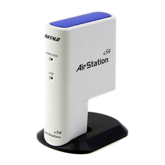
Buffalo AirStation WLI2-USB2-G54 User Manual
Wireless 54 mbps usb adapter with antenna interface
Hide thumbs
Also See for AirStation WLI2-USB2-G54:
- Specifications (2 pages) ,
- Specifications (2 pages)

Related Manuals for Buffalo AirStation WLI2-USB2-G54


Summary of Contents for Buffalo AirStation WLI2-USB2-G54
-
Page 1: User Manual
User Manual Wireless 54 Mbps* USB Adapter with Antenna Interface WLI2-USB2-G54 www.buffalotech.com/wireless... - Page 2 802.11g Wireless 54 Mbps* USB Adapter Windows XP – Installation & Configuration 1. Installing the Wireless 54 Mbps* USB Adapter Drivers: Introduction ◗ Insert the AirNavigator CD into the CD-ROM drive of the PC. The Air Navigator Setup Wizard launches automatically.
- Page 3 Introduction ◗ Select Install Wireless Adapter. Click the OK button to begin the installation pro- cess. ◗ Review the Software License Agreement. Click the Yes but- ton to confirm your agreement with the terms and continue in- stalling the Wireless Notebook Adapter drivers.
- Page 4 2. Installing the Wireless 54 Mbps* USB Adapter: ◗ Power on the notebook PC and let it boot into Windows. Plug the Wireless USB Adapter into an available USB port on your PC. A USB 2.0 port should be selected if possible. Depending on the type of computer that the Wireless USB Adapter is being installed on, the USB ports can be located in different areas of the case.
- Page 5 ◗ If a window opens, stating that your driver does not pass Windows Logo testing, click the Continue Anyway button. When the Wireless 54 Mbps* USB Adapter is successfully installed, click the Finish button. Restart your PC if prompted. Introduction...
- Page 6 If the Wireless Zero Configuration Service is activated, Windows will scan for available wireless access points once the Wireless Notebook Adapter is properly installed. If Windows detects one or more access points, a net- working icon appears on the task bar. One or more wireless networks are available appears as a caption accompanying the icon.
- Page 7 Introduction ◗ Click the Advanced button to enter an SSID network name or WEP/WPA encryption key, if either is necessary. To add an SSID network name that is not available, click the Add button.
- Page 8 Authentication and Data Encryption for the wireless network. Enter and confirm the Network Key and Key Index. Click the OK button when finished. ■ Note: Buffalo Technology recommends that users of the Wireless Zero Configuration Service upgrade to the latest version freely available at: http://www.microsoft.com.
-
Page 9: Installation & Setup
Installation & Configuration 1. Installing the Wireless 54 Mbps* USB Adapter: Power on the notebook PC and let it boot into Windows. Plug the Wireless USB Adapter into an ◗ available USB port on your PC. A USB 2.0 port should be selected if possible. Depending on the type of computer that the Wireless USB Adapter is being installed on, the USB ports can be located in different areas of the case. - Page 10 2. Installing the Wireless 54 Mbps* USB Adapter-Drivers: ◗ Insert the AirNavigator CD. Click Next at the Welcome to the Found New Hardware Wizard. Select Search for a suitable driver for my device. Click the Next button to continue. ◗...
- Page 11 ◗ Windows will display a driver you can use with the Wireless USB Adapter. Click the Next button to continue. Installation / Setup ◗ Windows 2000: If the Digital Signature Not Found page opens, informing that no digital signature exists for the driver you are installing, click the Yes button to continue the installation process.
-
Page 12: Client Manager
Client Manager Use Client Manager to configure your wireless network. Use Client Manager to survey and connect to available access points, enable and use WEP encryption, and create connection profiles. ■ Note: Client Manager does not function properly if the Windows XP Wireless Zero Configuration Service is enabled. - Page 13 ◗ Once the Installer Wizard launches, click the Next button to begin the software installation. ◗ Press I Agree to accept the license agreement and continue the installation process. Client Manager...
- Page 14 ◗ Press the Exit button to exit the Client Manager installation utility. The Buffalo Client Manager is now installed ◗ and running, right clicking on its icon (the black notebook icon) will allow you to begin using it.
- Page 15 Client Manager. This page displays the status of the connection between the wireless adapter and another wireless device. This page only displays connection information no changes to the connection can be made from this screen.
- Page 16 • Signal Strength – Displays the strength of the signal. Signal Strength is based on the peak signal level the wireless adapter receives from the wireless device to which it is connected. Next to the signal level is the wireless hardware type that the computer has available.
- Page 17 Survey Page Click the Survey tab to open this page. Use this page to survey the area, display available access points, and connect to available access points. Note: The part number of the client device displayed in these screenshots is not reflective of your specific client device. Press the ‘Connect’...
- Page 18 Once the ‘Connect’ button is pressed, you will be prompted to enter any encryption related infor- mation. by the wireless network must be inputted. Please consult your wireless access point or router’s documentation for proper input of the encryption keys. Some wireless networks may require you to enter multiple keys, in this event, four separate fields are available for encryption keys.
- Page 19 Profiles Page allows you to delete a profile no longer used or required. • Add – Click the Add button to add a profile manually. You will need important information such as SSID, encryption settings, and network type. Client Manager Configuration Click the Profiles tab to open this page.
- Page 20 New Profile Dialog Box Use this dialog box to create a new profile. must use identical SSIDs to successfully associate with other devices on the network. MYSSID is an example of a valid SSID. • Channel – Displays the channel associated with the new profile. The channel indicates what range of frequencies the radio waves emitted by the wireless device are occupying.
- Page 21 Advanced Profile Options • Network Tab – Displays the network information tab. A static IP can be specified for this wire- less profile here. It is not recommended to change any of these settings unless specified by an administrator. • Browser Tab – Displays settings to change your browser preferences for this wireless profile. A specific home page can be specified when connected to this wireless profile as can specific proxy server addresses.
-
Page 22: Antenna Information
Antenna Information ◗ The WLI2-USB2-G54 comes with two internal diver- sity antennas. External antennas can be added on the rear of the unit by removing the rubber protector. * The antenna interface is MC connector. -
Page 23: Wireless Zero Configuration
Wireless Zero Configuration Wireless Zero Configuration Service (Windows XP) Windows XP offers the Wireless Zero Configuration Service to support 802.11b and 802.11g wire- less networking. This service automatically polls the area for available wireless access points. If an available wireless access point is found, Windows attempts to connect to the access point. If no available wireless access points are found, you must manually add the access points. -
Page 24: Specifications
Wireless LAN Interface Standards Compliance Communication Protocol Frequency Range Transmission Rate Access Mode Security Others Interface Power Consumption Environmental Operation Specifications IEEE802.11g Direct Sequence Spread Spectrum (DS-SS), Half Duplex 2.412-2.462Mhz 802.11g: 1, 2, 5.5, 11, 18, 24, 36, 48, 54Mbps (Auto) Infrastructure mode, Ad-Hoc 128/64 Bit WEP, WPA, 802.1x, WPA-PSK, TKIP, AES USB 2.0 (Compatible USB 1.1) - Page 25 Communication Range Speed 54Mbps 11Mbps 1Mbps All distances are estimated. Wireless connections may be affected as physical conditions and circumstances vary. Indoor 165 ft. (50m) 300 ft. (90m) 375 ft. (115m) Specifications Outdoor 525 ft. (160m) 1310 ft. (400m) 1750 ft. (550m)
-
Page 26: Troubleshooting (Faq)
Client Manager will not work properly with the G54 Wireless 54 Mbps* USB Adapter. Before updating Client Manager, you must uninstall all previous versions of Client Manager. To update your Client Manager, load the Air Navigator CD and select Install Client Manager. - Page 27 I have more than one Air Navigator CD. Do I need more than one CD? No. You receive the same Air Navagator CD with each Buffalo Technology access point and wire- less adapter. The CDs are identical and you only need one copy.
- Page 28 10BaseT or 100BaseTx: 802.3 based Ether- net network that uses UTP (Unshielded twisted pair) cable and a star topology. 10 is 10 Mbps and 100 is 100 Mbps. 802.1x: The standard for wireless LAN authenti- cation used between an AP and a client. 802.1x with EAP will initiate key handling.
- Page 29 Driver: Software that interfaces a computer with a specific hardware device. DSSS (Direct Sequence Spread Spectrum): Method of spreading a wireless signal into wide frequency bandwidth. DTE (Data Terminal Equipment): Device that controls data flowing to and from a computer. Dynamic IP Address: An IP address that is automatically assigned to a client station in a TCP/IP network, typically by a DHCP server.
- Page 30 IP (Internet Protocol) Address: A unique 32- binary-digit number that identifies each sender or receiver of information sent in packets. Infrastructure: A wireless network or other small network in which the wireless network devices are made a part of the network through the Access Point.
- Page 31 Packet: A block of data that is transferred as a single unit, also called a frame or a block. Packet Filtering: Discarding unwanted net- work traffic based on its originating address or its type. PCI (Peripheral Component Interconnect): A bus that is connected directly to the CPU. PCMCIA (Personal Computer Memory Card International Association) Card: Remov- able module that adds features to a portable...
- Page 32 ROM (Read Only Memory): Permanent memory. Router: Device that can connect individual LANs and remote sites to a server. Roaming: The ability to use a wireless device while moving from one access point to another without losing the connection. Script: A macro or batch file containing instruc- tions and used by a computer to perform a task.
- Page 33 Network) or other communications system. Twisted Pair: Cable that comprises 2 or more pair of insulated wires twisted together. UDP (User Datagram Protocol): A com- munication method (protocol) that offers a limited amount of service when messages are exchanged between computers in a network. UDP is used as an alternative to TCP/IP.
-
Page 34: Fcc / Ce Information
Federal Communication Commission Interference Statement This equipment has been tested and found to comply with the limits for a Class B digital device, pursuant to Part 15 of the FCC Rules. These limits are designed to provide reasonable protection against harmful interference in a residential installation. This equipment generates, uses and can radiate radio frequency energy and, if not installed and used in accordance with the instructions, may cause harmful interference to radio communications. -
Page 35: Important Note
FCC / CE Information IMPORTANT NOTE: FCC RF Radiation Exposure Statement: This equipment complies with FCC RF radiation exposure limits set forth for an uncontrolled environment. This equipment should be installed and operated with a minimum distance of 20 centimeters between the radiator and your body. This transmitter must not be co-located or operating in conjunction with any other antenna or transmitter. - Page 36 FCC / CE Information EU Countries intended for use The ETSI version of this device is intended for home and office use in Austria, Belgium, Denmark, Finland, France (with Frequency channel restrictions), Germany, Greece, Iceland, Ireland, Italy, Luxembourg, Norway, The Netherlands, Portugal, Spain, Sweden, Switzerland and United Kingdom.
-
Page 37: Warranty Information
fitness of a particular purpose are limited in duration to the above period. Under no circumstances shall Buffalo Technology (USA), Inc. be liable in any way to the user for damages, including any lost profits, lost savings or other incidental or consequential damages arising out of the use of, or inability to use the Buffalo products. -
Page 38: Contact Information
Contact Information ADDRESS Buffalo Technology (USA), Inc. 4030 West Braker Lane, Suite 120 Austin, TX 78759-5319 GENERAL INQUIRIES Monday through Friday 8:30am-5:30pm CST Direct: 512-794-8533 Toll-free: 800-456-9799 Fax: 512-794-8520 Email: sales@buffalotech.com TECHNICAL SUPPORT North American Technical Support by phone is available 24 hours a day, 7 days a week. (USA and Canada). - Page 39 4030 W. Braker Ln. Suite 120 Austin, Texas 78759 Tel: 800-456-9799 Fax: 512-794-8606 Technical Support is available 24 hours a day, 7 days a week (USA / Canada) Toll-Free: 866-752-6210 email: info@buffalotech.com ©2004, Buffalo Technology (USA), Inc.