Table of Contents
Advertisement
Quick Links
Indoor Environment
•
and Air Quality
Design Flexibility
•
Performance
•
Energy Efficiency
•
Serviceability
•
- Vertical floor or wall mounted for concealed or exposed applications
- Horizontal ceiling for exposed or partially exposed applications
- Hot water coils, steam coils, or electric heat only options
- Optional colors, valve packages, controls, and unit configurations
- Nominal CFM range of 200 to 1,200 CFM
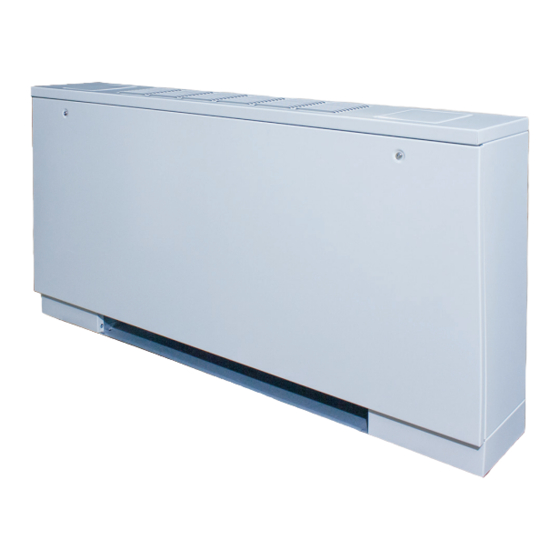
Cabinet Heater G*Y/D*Y Series
INSTALLATION, OPERATION, & MAINTENANCE MANUAL
GXY
Vertical & Horizontal
DBY
Advertisement
Table of Contents

Related Manuals for IEC G Y Series

Summary of Contents for IEC G Y Series
- Page 1 Cabinet Heater G*Y/D*Y Series INSTALLATION, OPERATION, & MAINTENANCE MANUAL Vertical & Horizontal Indoor Environment • and Air Quality Design Flexibility • Performance • Energy Efficiency • Serviceability • - Vertical floor or wall mounted for concealed or exposed applications - Horizontal ceiling for exposed or partially exposed applications - Hot water coils, steam coils, or electric heat only options - Optional colors, valve packages, controls, and unit configurations - Nominal CFM range of 200 to 1,200 CFM...
- Page 2 Cabinet Heater G*Y/D*Y Series INSTALLATION, OPERATION, & MAINTENANCE MANUAL It is the responsibility of the end user to properly characterize and dispose of all waste materials according to applicable regulatory and legal entities. Where reasonable, safe, and compliant with local regulatory and legal requirements, IEC encourages recycling materials when disposing of its products. International Environmental Corporation (IEC) works continually to improve its products. As a result, the design and specifications of each product may be changed without notice and may not be as described herein. Please contact IEC for information regarding current design and product specifications. Statements and other information contained herein are not express warranties and do not form the basis of any bargain between the parties but are merely IEC’s opinion or commendation of its products. Manufacturer’s standard limited warranty applies.
-
Page 3: Table Of Contents
Cabinet Heater G*Y/D*Y Series INSTALLATION, OPERATION, & MAINTENANCE MANUAL Table of Contents SECTION ONE — Installation SECTION THREE — Controls Operation Preface Board Components and Specifications Unpacking and Inspection Board Function and Diagnostics Prepare Jobsite and Units LED Functions and Outcomes (sequence of operations) Handling and Installation Wiring Diagrams... -
Page 4: Section One - Installation
Cabinet Heater G*Y/D*Y Series INSTALLATION, OPERATION, & MAINTENANCE MANUAL SECTION ONE — Installation nitrogen to avoid possible damage or injury in the event of Preface a leak or component failure during testing. International Environmental Corporation cabinet heater units represent a prudent investment offering trouble- Always protect adjacent flammable material when free operation and long service with proper installation, welding or soldering. Use a suitable heat shield material to operation, and regular maintenance. Your equipment is contain sparks or drops of solder. Have a fire extinguisher initially protected under the manufacturer’s standard readily available. warranty; however, this warranty is provided under All mechanical and electrical connections should be made the condition that the steps outlined in this manual for by authorized personnel in accordance with National and initial inspection, proper installation, regular periodic local codes where applicable. The manufacturer assumes maintenance, and everyday operation of the equipment no responsibility for personal injury or property damage be followed in detail. This manual should be fully reviewed resulting from improper or unsafe practices during in advance before initial installation, start-up, and any the handling, installation, service, or operation of any maintenance. Should any questions arise, please contact equipment. your local Sales Representative or the factory BEFORE proceeding. -
Page 5: Prepare Jobsite And Units
At the time of receipt, the equipment type and outs during handling. Also, depending on the options arrangement should be verified against the order and accessories, some units could contain delicate documents. Should any discrepancy be found, the local components that may be damaged by improper handling. IEC Factory Representative should be notified immediately Wherever possible, all units should be maintained in an so that proper action may be taken. upright position, and handled by the chassis, plenum NOTE: Should any questions arise concerning warranty sections, or as close as possible to the mounting-point repairs, the factory must be notified BEFORE any locations. In the case of a full cabinet unit, the unit must corrective action is taken. obviously be handled by the exterior casing. This is acceptable providing the unit is again maintained in an Prepare Jobsite and Units upright position, and no force is applied that may damage internal components or painted surfaces. -
Page 6: Unit Clearance And Service Access
Cabinet Heater G*Y/D*Y Series INSTALLATION, OPERATION, & MAINTENANCE MANUAL SECTION ONE — Installation, Cont’d. Unit Clearance and Service Access For specific unit dimensions, refer to Technical Catalog CA-010 submittal drawings for your model. Provide adequate clearance for the removal of the panel, access to controls or replacement of internal serviceable components including air filters. Allow clearances according to local and national codes. Service access is available from the front on vertical units. Cabinet and recessed units have removable front panels to allow access to the unit. Hydronic Heat units have either right or left hand piping. Reference piping locations by facing the front of the unit (airflow discharges from the front). The control panel is always on the end opposite the piping. See Figures 1 and 2 for recommended service and operating clearances. 8 in. from flange both sides Figure 1. Vertical Concealed (GHY) Table 1. Vertical Floor (GHY and GXY/GSY) Size GXY/GSY 23-1/2 (597) - Page 7 Cabinet Heater G*Y/D*Y Series INSTALLATION, OPERATION, & MAINTENANCE MANUAL SECTION ONE — Installation, Cont’d. Table 2. Horizontal Ceiling Coil Removal Minimum Service Clearance Width Size 37 (940) 38 (965) 37 (940) 42 (1067) 43 (1092) 48 (1219) 55 (1397) 53 (1346) 55 (1397) 60 (1524) 77 (1956) 74 (1880) 77 (1956) 83 (2083) 28 in. Figure 3.
-
Page 8: Vertical Series Unit Installation
Cabinet Heater G*Y/D*Y Series INSTALLATION, OPERATION, & MAINTENANCE MANUAL SECTION ONE — Installation, Cont'd. Vertical Series Unit Installation Wall Mount Figure 5. Wall Mount Hanger Hole Locations – GHY GHY, GXY, GSY Vertical unit models are designed to be floor mounted or otherwise supported from below and bolted to the wall or floor structure through the mounting holes provided in the chassis. These units may be wall mounted only when originally ordered from the factory for wall-mount applications. The type of mounting device is a matter of choice; however, the mounting point shall always be that provided in the chassis or cabinet. Fasteners and other required hardware must be field-supplied. Refer to the unit product drawings for hole mounting locations and sizes. -
Page 9: Cabinet Front Panel Installation And Removal
Cabinet Heater G*Y/D*Y Series INSTALLATION, OPERATION, & MAINTENANCE MANUAL SECTION ONE — Installation, Cont'd. 4. For Cabinet Units (GXY, GSY), remove the front Table 4. Style W & Z Framed Wall Panel Dimensions panel before installation. Panel Wall Opening Frame Width Nominal Width (A) Inches (mm) 5. Mount the unit on the hanger hardware. Test to Inches Inches (mm) Width Height... - Page 10 Cabinet Heater G*Y/D*Y Series INSTALLATION, OPERATION, & MAINTENANCE MANUAL SECTION ONE — Installation, Cont'd. Figure 8. Style W Framed Wall Panel Install Diagram Figure 10. Style Z Framed Wall Panel Install Diagram Figure 9. Style Z Framed Wall Panel Style Z...
-
Page 11: Installation (Ghy)
Cabinet Heater G*Y/D*Y Series INSTALLATION, OPERATION, & MAINTENANCE MANUAL SECTION ONE — Installation, Cont'd. Optional Trim Kit Installation Horizontal Series Unit Installation An optional trim kit can be applied to partially recess the DBY, DXY GXY, GSY units in the wall. The trim kit can also be applied Anchoring the equipment in place is accomplished by to cover rough opening to eliminate the need for finish using the mounting points provided with 3/8” all-thread work such as carpentry, drywall, painting, etc. rod and other hardware (not supplied with unit). The unit must be positioned so that the coil or electric heat Reference unit submittal drawings for unit sizes. Trim kits elements are on a LEVEL PLANE. have 1" flanges. Other field-furnished mounting devices such as rubber- There are 3 mounting brackets (two sides, one top) in-shear or spring-type vibration isolators selected by the provided in the trim kit for floor mount units. There are contractor or engineer may be substituted for the factory 4 mounting brackets (two sides, top, bottom) in the trim grommets and should be used where factory grommets kit for wall mount units. There are no mounting holes... -
Page 12: Hydronic Heating Connections
Cabinet Heater G*Y/D*Y Series INSTALLATION, OPERATION, & MAINTENANCE MANUAL SECTION ONE — Installation, Cont'd. Hydronic Heating Connections If coil and valve package connections are to be made with a “sweat” or solder joint, care should be taken to After mounting the unit, it is then ready for the various assure that no components in the valve package are service connections such as water and electrical. At this subjected to a high temperature which may damage time, it should be verified that the proper types of services seals or other materials. Many two-position electric are actually provided to the unit. On those units requiring control valves, depending on valve operation, are hot water, the proper line size and water temperature provided with a manual opening lever. This lever should be available to the unit. should be placed in the “open” position during all CAUTION: Toxic residues and loose particles soldering or brazing operations. resulting from manufacturing and field piping Ground-Joint seal preparation for copper unions techniques such as joint compounds, soldering flux, and (recommended by manufacturer):... -
Page 13: Electrical Connections
Cabinet Heater G*Y/D*Y Series INSTALLATION, OPERATION, & MAINTENANCE MANUAL SECTION ONE — Installation, Cont'd. Label each tube extension for purpose, i.e: In the event that leaking or defective components are "HS" for Heating Supply, etc. Solder tube discovered, the Sales Representative must be notified extensions to the valve package. BEFORE any repairs are attempted. All leaks should be repaired before proceeding with the installation. 2. Remove valve actuators temporarily during valve installation. Protect unit wiring from After system integrity has been established, insulate the damage. piping in accordance with the project specifications. This is 3. Install valve package. the responsibility of the installing or insulation contractor. 4. Torque unions tight using backup wrench to Electrical Connections prevent damage to coil tubes. Align exiting The electrical service to the unit should be compared to tubes to the center of the pipe openings. the unit nameplate to verify compatibility. The routing 5. If desired, apply split bushings or grommets and sizing of all piping, and the type and sizing of all (provided by others) to the pipes for... - Page 14 Cabinet Heater G*Y/D*Y Series INSTALLATION, OPERATION, & MAINTENANCE MANUAL SECTION ONE — Installation, Cont'd. The fan motor(s) should never be controlled by any wiring 2. Determine appropriate knock out to feed incoming or device other than the 3-speed switch or thermostat/ power wiring into box. switch combination without factory authorization. 3. Loosen screws to rotate cover plate to access Fan motor(s) may be temporarily wired for use during wiring. construction only with prior factory approval in strict Figure 15. Loosened covered plate accordance with the instructions issued at that time. All field wiring should be done in accordance with governing codes and ordinances. Any modification of the unit wiring without factory authorization will void all of the factory warranties, and will nullify any agency listings. The manufacturer assumes no responsibility for any damages and/or injuries resulting from improper field installation and/or wiring. 1. After planning for and bringing incoming power to the unit, locate the control box and cover plate (incoming electrical power wiring compartment).
-
Page 15: Ductwork Connections
Cabinet Heater G*Y/D*Y Series INSTALLATION, OPERATION, & MAINTENANCE MANUAL SECTION ONE — Installation, Cont'd. 4. Secure incoming power wiring with proper Figure 18. Thermostat unit-mount service entrance connector and/or appropriate *NOTE – Image below depicts control box with Venture Wi-Fi Thermostat strain relief. Use wire nuts connections that meet wire gauge requirements. 5. Replace cover plate and secure screws. Figure 16. External unit-mount control box access Ductwork Connections All ductwork and/or supply and return grilles should be installed in accordance with the project plans and specifications. If not included on the unit or furnished from the factory, supply and return grilles should be provided as Figure 17. Unit-mounted control box access recommended in the product catalog. -
Page 16: Final Preparations
Cabinet Heater G*Y/D*Y Series INSTALLATION, OPERATION, & MAINTENANCE MANUAL SECTION ONE — Installation, Cont'd. The manufacturer assumes no responsibility for undesirable system operation due to improper design, equipment or component selection, and/or installation of base unit, ductwork, grilles, and other related components. Final Preparations 1. Turn off power to the unit (open unit electrical disconnect) and install lockout tags on all power supplies to unit. 2. Install thermostats and perform any other final wiring as applicable. Ensure all electrical connections are tight. 3. Perform a final visual inspection. All equipment, plenums, ductwork, and piping should be inspected to verify that all systems are complete and properly installed and mounted, and that no debris or foreign articles such as paper or drink cans are left in the units or other areas. Clean dirt, dust, and other construction debris from unit interior. Be sure to check fan wheel and housing and clean, if necessary. 4. Rotate fan wheel by hand to be sure it is free and does not rub housing. Check that wing nuts securing fan assembly to fan deck are tight. Adjust if necessary. -
Page 17: Section Two - Start-Up
Cabinet Heater G*Y/D*Y Series INSTALLATION, OPERATION, & MAINTENANCE MANUAL SECTION TWO — Start-Up and metering devices. Strainers should be installed in the General Start Up piping mains to prevent this material from entering the Before beginning any start-up operation, the start-up units during normal operation. personnel should familiarize themselves with the unit, options and accessories, and control sequence to During system filling, air venting from the unit is understand the proper system operation. All personnel accomplished by the use of the standard, manual air vent should have a good working knowledge of general fitting, or the optional, automatic air vent fitting installed. start-up procedures and have the appropriate start-up To vent the air from the coil, depress the valve until the air and balancing guides available for consultation. has vented the coil. When water begins to escape through the valve, release the valve. Automatic air vents may be The building must be completely finished including doors, unscrewed one turn counterclockwise to speed initial windows, and insulation. All internal walls and doors venting, but should be screwed in for automatic venting should be in place and in the normal position. In some after start-up operations. cases the interior decorations and furniture may influence overall system performance. The entire building should CAUTION! The air vent provided on the unit is be as complete as possible before beginning any system not intended to replace the main system air vents... -
Page 18: Water Treatment
Cabinet Heater G*Y/D*Y Series INSTALLATION, OPERATION, & MAINTENANCE MANUAL SECTION TWO — Start-Up, Cont'd. Water Treatment Water System Balancing Proper water treatment is a specialized industry. IEC A complete knowledge of the hydronic system, along with recommends consulting an expert in this field to analyze its components and controls, is essential to proper water the water for compliance with the water quality parameters system balancing. This procedure should not be attempted listed below, and to specify the appropriate water treatment by unqualified personnel. The system must be complete, regimen. The expert may recommend typical additives such and all components must be in operating condition as rust inhibitors, scaling preventative, antimicrobial growth BEFORE beginning water system balancing operations. agents, or algae preventatives. Antifreeze solutions may Each hydronic system has different operating characteristics also be used to lower the freezing point. depending on the devices and controls used in the system. IEC water coil tubes and headers are constructed of pure The actual balancing technique may vary from one system copper. Multiple brass alloys may be present in the valve to another. package, depending on unit configuration. It is the user’s... - Page 19 Cabinet Heater G*Y/D*Y Series INSTALLATION, OPERATION, & MAINTENANCE MANUAL SECTION THREE – Controls Operation 85 Control Board (E025-71481108) Changeover/Return Air Sensor (CN2) Remote Shutdown Input (CN3) Pluggable T-Stat Connector (CN1) Overflow Switch (CN4) LED Indication(s) ECM Fan Speed Adjustment ECM Connection (CN10) Two-Stage Cooling (CN5) Actuator &...
-
Page 20: Board Function And Diagnostics
Cabinet Heater G*Y/D*Y Series INSTALLATION, OPERATION, & MAINTENANCE MANUAL SECTION THREE – Controls Operation, Cont'd. Board Function and Diagnostics 1. CN1 – 24V Customer Input (Thermostat) Use proper wire gauge and insulation type based on application and local code requirements. For detailed IEC 24V thermostat control wiring diagrams, reference thermostat IOMs. For Factory Installed IEC 24V Thermostat* * Does not apply to proportional or Line voltage thermostat controls. The diagram below represents a factory installed IEC 24V thermostat. Connection Function/Description (+) 10V Not used (-) COM... - Page 21 Apply 24V for Stage 1 heat W1 / HTG Apply 24V for Stage 1 cool Y1 / CLG Apply 24V for Stage 2 heat W2 / HT2 Apply 24V for Stage 2 cool Y2 / CL2 24V Controller Power R / 24V Changeover sensor Room air sensor 2. CN2 – Changeover/Return Air Sensor Power connector for 24V or Common-powered sensors 24V powered sensors Applicable for IEC-supplied air sensor for Wi-Fi (E055-71520330), Programmable (E055-71520317), Non-programmable (E055-71520316) 24V IEC thermostats Common-powered sensors Applicable for thermostats by others Sensor/switch 10k thermistor Bimetal switch 3. CN3 – Remote Shutdown Input Provides dry contact for signal to BAS system – I/O Dry Normally Open Wet Normally Open Discrete Coil When contact activated Motor OFF Actuator OFF...
- Page 22 Switch is normally closed and opens on an increase in water level. When contact activated, then a. Motor OFF b. Valve Actuator OFF c. Electric Heat OFF d. Power to controller remains ON OVF LED indication when condensate switch activated 5. CN5 – 2nd Stage Cooling/Heating Available with two stage coil for part load a. Available with IEC Venture Wi-Fi Thermostat (E055-71520330). Contact factory for application. 24V On/Off, 24V Floating, 0-10V Proportional control CL2 or HT2 LED indication when either 2 stage cooling or heating activated 6. CN6 – 1st Stage Cooling/Heating 24V On/Off, 24V Floating, 0-10V Proportional control, Line voltage SureFlow control available. Contact factory for applications CLG or HTG LED indication when either 1 stage cooling or heating activated 7. CN7 – Class II Transformer...
- Page 23 Cabinet Heater G*Y/D*Y Series INSTALLATION, OPERATION, & MAINTENANCE MANUAL SECTION THREE – Controls Operation, Cont'd. 11. ECM Fan Speed Adjustment, cont'd. Figure 22. 3-Speed, Potentiometer Adjustment (ECO V 2 Only) (E025-71481108) Potentiometers Note: The unit has been factory configured to produce PSC equivalent airflow on high speed, with medium and low speed set at 80% and 60% of high, respectively. If these setting are acceptable, then no further configuring is required. If alternative airflows are desired, use board mounted pots to adjust the airflow associated with each input. To reset to initial factory settings, reference the voltages found on the sticker next to the pots. Each output can be adjusted from 0 to 100% of the motor’s factory programmed operating range. Increasing the voltage increases airflow, decreasing the voltage decreases airflow. Adjusting the potentiometers requires the use of a Multi-meter capable of measuring 0~5 vdc. 1. Only trained and qualified individuals should attempt to adjust or service components on any electrical component. Failure to follow safety rules could result in electrical shock or hazard.
- Page 24 Cabinet Heater G*Y/D*Y Series INSTALLATION, OPERATION, & MAINTENANCE MANUAL SECTION THREE – Controls Operation, Cont'd. 11. ECM Fan Speed Adjustment, cont'd. Variable Airflow for 0-10 VDC If a factory provided thermostat or DDC controller is utilized, then the unit is already correctly configured. Eco 2 Variable Airflow for 0-10 VDC No control board is required and no field adjustments are possible. Motor uses 0-10VDC signal directly. See control box label. Fan enable at 1.5VDC. 12. Ground Tab Connection For mulitmeter diagnostics...
-
Page 25: Led Functions And Outcomes (Sequence Of Operations)
Cabinet Heater G*Y/D*Y Series INSTALLATION, OPERATION, & MAINTENANCE MANUAL SECTION THREE – Controls Operation, Cont'd. 13. LED Functions and Outcomes (Sequence of Operations) Item Description Outcome • OVF LED Shows Red Condensate • Motor OFF Overflow Switch Condensate switch is tripped by increasing water level in the drain pan • Actuator OFF (OVF) • Electric Heat Off • Power to controller remains ON •... - Page 26 Cabinet Heater G*Y/D*Y Series INSTALLATION, OPERATION, & MAINTENANCE MANUAL SECTION THREE – Controls Operation, Cont'd. Example Wiring Diagram – Electric Heat Only *NOTE – Wiring diagram also available through QR code found on the unit serialized name plate label.
- Page 27 Cabinet Heater G*Y/D*Y Series INSTALLATION, OPERATION, & MAINTENANCE MANUAL SECTION THREE – Controls Operation, Cont'd. Example Wiring Diagram – 2 Pipe, Hydronic Heat Only *NOTE – Wiring diagram also available through QR code found on the unit serialized name plate label.
-
Page 28: Section Four - Normal Operation And Maintenance
Cabinet Heater G*Y/D*Y Series INSTALLATION, OPERATION, & MAINTENANCE MANUAL SECTION FOUR – Normal Operation and Maintenance SECTION FOUR – Normal Operation & Bipolar Ionizer Brush Cleaning The bipolar ionizer is designed to not require replacements Periodic Maintenance parts. General The brushes on the device may become dirty over time Each unit on a job will have its own unique operating and will require cleaning to maintain the effectiveness environment and conditions which may dictate a of ion output. Cleaning of bipolar ionizer brushes and maintenance schedule for that unit that is different inspection of device should be performed at time of from other equipment on the job. A formal schedule of each filter change or sooner, based on the location, filter regular maintenance and an individual unit log should be effectiveness and general environment. -
Page 29: Coil
Cabinet Heater G*Y/D*Y Series INSTALLATION, OPERATION, & MAINTENANCE MANUAL SECTION FOUR – Normal Operation and Maintenance, Cont'd. Coil Figure 25. Vertical series electric heater w/protective heatshield *NOTE – Figure 23 depicts GXY. Size and number of elements varies with model. Coils may be cleaned by removing the motor/blower assemblies and brushing the entering air face between fins with a stiff brush. Brushing should be followed by cleaning with a vacuum cleaner. If a compressed air source is available, the coil may also be cleaned by blowing air through the coil fins from the leaving air face. This should again be followed by vacuuming. Units provided with the proper type of air filters, replaced regularly, will require less frequent coil cleaning. Electric Heater Assembly Electric heaters typically require no normal periodic Figure 26. -
Page 30: Valves And Piping
Cabinet Heater G*Y/D*Y Series INSTALLATION, OPERATION, & MAINTENANCE MANUAL SECTION FOUR – Normal Operation and Maintenance, Cont'd. When replacing any components such as fuses, Filters, Permanent contactors, or relays, use only the exact type, size and A maintenance schedule for permanent filters should voltage component as furnished from the factory. Any be developed in the same manner as throwaway filters. deviation without factory authorization could result in Unlike throwaway filters, permanent filters may be personnel injury or damage to the unit. This will also cleaned and re-installed in the unit instead of being void all factory warranties. All repair work should be discarded when dirty. The optional factory permanent done in such a manner as to maintain the equipment in filter may be cleaned in hot soapy water to remove any compliance with governing codes, ordinances and testing trapped dirt. It should then be set aside on edge to dry. agency listings. Before replacing the filter in the unit, it should be More specific information regarding the use and operating recharged with some type of entrapment film such as characteristics of the standard controls offered by the “Film-Cor Recharging Oil.” The filter should be sprayed on manufacturer are contained in other manuals. -
Page 31: Replacement Parts
Cabinet Heater G*Y/D*Y Series INSTALLATION, OPERATION, & MAINTENANCE MANUAL SECTION FOUR – Normal Operation and Maintenance, Cont'd. Replacement Parts Factory replacement parts should be used wherever possible to maintain unit performance, it’s normal operating characteristics, and the testing agency listings. Replacement parts may be purchased through a local Sales Representative. Contact the local Sales Representative or the factory before attempting any unit modifications. Any modifications not authorized by the factory could result in personnel injury, damage to the unit, and could void all factory warranties. When ordering parts, the following information must be supplied to ensure proper part identification: (1) Complete unit model number (2) Unit serial number (3) Complete part description, including any numbers For warranty parts inquiries, in addition to the information previously listed, a description of the issue with the parts is required. Contact the factory for authorization to return any parts, such as defective parts, to be replaced in warranty. -
Page 32: Section Five - Equipment Start-Up
Cabinet Heater G*Y/D*Y Series INSTALLATION, OPERATION, & MAINTENANCE MANUAL SECTION FIVE – Equipment Start-Up Checklist IMPORTANT Fan coil units must be filled with water before operating the circulator. The circulator bearings are water lubricated and should not be allowed to operate dry. Filling the system properly will result in immediate lubrication of the bearings. Receiving and Inspection Ductwork Connections Unit received undamaged Install ductwork, fittings and grilles, as required Unit received complete as ordered Flexible duct connections at unit “Furnish only” parts accounted for Proper supply and return grille type and size Unit arrangement/hand correct Control outside air for freeze protection Unit structural support complete and correct Insulate all ductwork, as required ... -
Page 33: Terms And Conditions
15. Payment terms are net thirty (30) days from date of shipment on approved credit. One and one (1) All complete fan coil units built or sold by IEC for twelve (12) months from date of unit start half percent (1 1/2%) per month (18% annual rate) may be charged on past due accounts or the up or eighteen (18) months from date of shipment (from factory), whichever comes first. - Page 34 Cabinet Heater G*Y/D*Y Series INSTALLATION, OPERATION, & MAINTENANCE MANUAL This page intentionally left blank.
- Page 35 Cabinet Heater G*Y/D*Y Series INSTALLATION, OPERATION, & MAINTENANCE MANUAL This page intentionally left blank.
- Page 36 Cabinet Heater G*Y/D*Y Series INSTALLATION, OPERATION, & MAINTENANCE MANUAL Contact your local IEC Sales Representative for further details and pricing applicable to this product. Visit our website (iec-okc.com) to find your local IEC Sales Rep. 5000 W. I-40 Service Rd. IEC Part Number: I100-90034485 Oklahoma City, OK 73128 P: 405.605.5000 IOM-010 Rev. 2 (07/2021) F: 405.605.5001 ©2021 International Environmental Corporation (IEC) www.iec-okc.com...
Need help?
Do you have a question about the G Y Series and is the answer not in the manual?
Questions and answers