Table of Contents
Advertisement
Quick Links
Advertisement
Table of Contents

Related Manuals for Red Panda BITMAP 2


Summary of Contents for Red Panda BITMAP 2
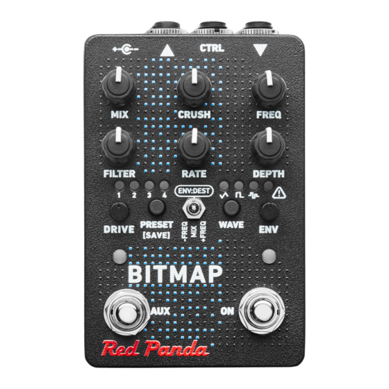
- Page 1 BITMAP 2 Owner’s Manual Plymouth, MI • www.redpandalab.com...
- Page 2 Bitmap 2 Owner’s Manual Version 2.0 (firmware 2.0+) March 2021 Red Panda LLC 44712 Helm St Plymouth, MI 48170 ©2021 Red Panda LLC www.redpandalab.com...
- Page 3 Please register your product at redpandalab.com/register Product manuals and firmware updates are available at redpandalab.com/downloads For technical support, email support@redpandalab.com...
-
Page 4: Table Of Contents
Contents Introduction Signal Flow Getting Started Inputs and Outputs Controls What the LEDs Mean ON Switch AUX Switch Bitcrushing Waveshaping Filter Low Frequency Oscillator (LFO) Envelope Follower (ENV) Web Editor Control Input Using MIDI Reset to Factory Defaults Firmware Updates Support and Repairs Warranty Specifications... -
Page 5: Introduction
Thank you for purchasing the Bitmap 2. The first Red Panda product was a bitcrusher module released in 2009 for the Line 6 ToneCore® dock. The Bitmap 1 was released in 2014 and featured an updated bitcrushing algorithm, but had fewer fea- tures than the 2009 bitcrusher due to hardware limitations. -
Page 6: Signal Flow
Signal Flow WAVE FOLDER WAVE WINDOW WAVE SHAPER DRIVE CLIP BITS FILTER MIXER Bit crushing and waveshaping are amplitude-dependent effects, so it is helpful to be familiar with gain staging. Gain staging is adjusting the signal level at each point in the signal path - usually to maximize signal-to-noise ratio without distortion. -
Page 7: Getting Started
Getting Started This section is coming soon. Web Editor We provide a web-based editor to configure your Bitmap, access hidden parameters, and fine-tune pre- sets. See "Web Editor (beta)" on page 13 for more information.. It requires the Google Chrome brows- er, and can be accessed at https://www.redpandalab.com/content/apps/bitmap-editor/index.html Note the "https"... -
Page 8: Inputs And Outputs
Inputs and Outputs DC POWER Connect a 9V DC center negative power supply rated at 250 mA or higher. USB mini B connector for MIDI, web editor, and firmware updates. 1/4" TRS mono or stereo input. CTRL 1/4" TRS jack for expression pedal, remote, tap tempo, or MIDI. 1/4"... -
Page 9: Controls
Controls Adjusts the wet/dry mix, from 100% dry to 100% wet. CRUSH Adjusts the bit depth from 24 bits down to 1 bit, including fractional bit depths. FREQ Adjusts the sampling rate, from 48,000 Hz down to 110 Hz. The sampling rate can be modulated by the LFO or envelope follower. -
Page 10: What The Leds Mean
• LFO modulation amount (±) • wavefolding threshold and number of folds • wave window position and width • waveshaping function The LFO modulates the sampling rate (FREQ) by default, but can be assigned to the filter cutoff (FILTER) or wet/dry blend (MIX) using our web editor or MIDI. The destination is stored in presets. DRIVE Adjusts the input gain from 0 dB to +40 dB. -
Page 11: On Switch
ON Switch The ON footswitch engages or bypasses the effect. A short press will switch between on and bypass (latching). When the pedal is in bypass, pressing and holding the ON switch will momentarily engage the effect, returning to bypass when the switch is released. The latching on/off state is remembered when power is off. -
Page 12: Bitcrushing
Bitcrushing This section is coming soon. Waveshaping This section is coming soon. Filter This section is coming soon. Low Frequency Oscillator (LFO) This section is coming soon. Envelope Follower (ENV) This section is coming soon. -
Page 13: Web Editor
Web Editor The web editor can be used to configure your pedal, access hidden parameters, and fine-tune presets. It is intended for "offline" configuration and editing. For live performance editing, we recommend using dedicated MIDI hardware or software and MIDI control change messages. Connect your pedal to a computer using a USB cable and go to the web editor URL using Chrome: https://www.redpandalab.com/content/apps/bitmap-editor/index.html Note the https in the URL. - Page 14 This tab also displays the installed firmware version and the input power supply (PSU) voltage. A low PSU voltage may indicate that the power supply is not able to provide enough current to properly power the pedal. Help The Show MIDI Devices button on the Help tab will display all of the MIDI devices accessible by your browser.
-
Page 15: Control Input
Control Input The CTRL (control) input supports different methods of remotely controlling the pedal: • Expression pedal • Control voltage (CV) with 0-3.3V range • Tap Tempo • TRS MIDI in (tip active) • Remote switch To configure a expression pedal or remote switch, hold down the right footswitch while plugging it in. The pedal will detect which device is connected using the steps below. - Page 16 Control Voltage Control voltage input is configured the same way as an expression pedal. CV Range: 0-3.3V (with over/under-voltage protection) Tip: 0-3.3V input Ring: 3.3V output (with current limiting) Sleeve: ground The expression input has current limiting in case you use a TS cable, but it is preferable to use a 1/4” TRS cable with the ring unconnected.
- Page 17 Remote Modes Mode Switch Function LED Indication Preset 1 Blinks green when saved Double tap: manual settings Hold (4 sec): save Preset 2 Blinks green when saved Double tap: manual settings Hold (4 sec): save Preset 3 Blinks green when saved Double tap: manual settings Hold (4 sec): save Preset 4...
-
Page 18: Using Midi
Using MIDI Your pedal supports USB MIDI (in/out) and 1/4" TRS MIDI (input only). USB MIDI Your pedal is a class-compliant USB device, which allows you to: • Control all parameters • Access additional hidden parameters The pedal can work with any USB MIDI host, including: •... - Page 19 MIDI Timing Clock MIDI timing clock messages are used to synchronize multiple MIDI devices to a single clock transmitter. The clock is typically provided by a DAW in computer-based setups and a sequencer or drum machine in hardware-only setups. Dedicated MIDI clock generators are available for more complicated setups that need tight synchronization, and some devices can convert between MIDI clock, DIN sync, and taps.
- Page 20 MIDI real time messages are high-priority messages that can interrupt other MIDI messages to ensure the best possible syncronization timing. However, the accuracy of the clock depends on the transmit- ter and any devices it passes through. It is common to have +/-1 milliseconds of jitter, with is irregular timing due to individual clock ticks arriving too early or too late.
- Page 21 MIDI Continuous Controller Messages CC Num Destination Notes Expression pedal CTRL input Crush Freq Modulation depth Modulation rate Envelope mod amount Filter cutoff Filter resonance * Drive AUX footswitch Use gated mode to send 127 on press and 0 on release. Matches footswitch behavior.
- Page 22 CC Num Destination Notes Modulation destination * Freq (default) (Receive only) Filter cutoff Envelope destination Mix - (towards dry) * Freq up Freq down Filter cutoff * LFO hold 0-63 64-127 Modulation note division See “Note Divisions” table Receive MIDI clock (global) 0-63 64-127 On (default)
- Page 23 Note Division Continuous Controller Values CC Value Note Division Off (tap tempo disabled) 8 measure 7 measures 6 measures 5 measures 4 measures 3 measures 2 measures 2 measure triplet Dotted whole note Whole note Whole note triplet Dotted half note Half note Half note triplet Dotted quarter note Quarter note...
- Page 24 Bitmap. The basic format is the same for all messages: Byte (hex) Description System Exclusive (SysEx) Red Panda ID byte 1 Red Panda ID byte 2 Red Panda ID byte 3 Bitmap family ID Bitmap product ID...
- Page 25 Properties Firmware Version ID 1 ID 2 Data Bytes Data Firmware version: 0: Major 1: Minor 2: Patch 3: Release type (ascii) 4-7: Build number Returns the firmware version. Input voltage ID 1 ID 2 Data Bytes Data 100 * PSU voltage in Volts Returns the approximate input voltage.
-
Page 26: Reset To Factory Defaults
Reset to Factory Defaults Use the following procedure to reset the Bitmap's configuration data to factory default settings. This will erase any advanced configuration and control port settings, but presets will not be affected. Note that this is rarely useful for troubleshooting problems with your pedal. 1. -
Page 27: Firmware Updates
Firmware Updates The Bitmap's firmware can be updated via drag and drop using any Mac or PC. No driver or special soft- ware is required. To tell which version of firmware your pedal is running: 1. Hold down the AUX (left) footswitch and connect power. 2. -
Page 28: Support And Repairs
Support and Repairs Technical Support Please register your product at redpandalab.com/register within 30 days of purchase. For technical support, send your question via email to support@redpandalab.com or use the contact form on our web site. Be sure to include your serial number. We are a small company with limited re- sources for technical support, so it might take us a few days to reply. -
Page 29: Warranty
Product within thirty (30) days of receipt. You are solely responsible for the payment of shipping costs and expenses to ship the Product to Red Panda. Red Panda will pay the cost of ship- ping the repaired or replacement Product to you. If the Product is returned for service and/or repairs, Red Panda will complete the repairs within sixty (60) days of receipt and ship the Product back to you. -
Page 30: Specifications
Specifications Maximum input level: +8 dBu Frequency response: 20-20 kHz, +0/-0.5 dB Input impedance: 1 MΩ Output impedance: < 1 kΩ Bypass: analog buffered Power supply: 9V DC, center negative Power connector: 2.1mm I.D. x 5.5mm O.D. barrel connector Power consumption: 250 mA Dimensions: 78 (W) x 124 (D) x 59 (H) mm...
Need help?
Do you have a question about the BITMAP 2 and is the answer not in the manual?
Questions and answers