Table of Contents
Advertisement
Quick Links
Advertisement
Table of Contents

Related Manuals for Red Panda RASTER 2


Summary of Contents for Red Panda RASTER 2
- Page 1 RASTER 2 Stereo Delay With Pitch Shifter Plymouth, MI • www.redpandalab.com...
- Page 2 Raster 2 Owner’s Manual Version 2.0 (firmware 2.0+) October 2021 Red Panda LLC 44712 Helm St Plymouth, MI 48170 ©2021 Red Panda LLC www.redpandalab.com...
- Page 3 Please register your product at redpandalab.com/register Product manuals and firmware updates are available at redpandalab.com/downloads For technical support, email support@redpandalab.com...
-
Page 4: Table Of Contents
Contents Introduction Signal Flow Front Panel Getting Started Inputs and Outputs Raster 2 Controls Control Input Web Editor Reset to Factory Defaults Effects Design With the Raster 2 Using MIDI Support, Repairs, and Warranty Firmware Updates Specifications Credits... -
Page 5: Introduction
Introduction Thank you for purchasing the Raster 2. The Raster™ is a digital delay with a pitch and frequency shifter integrated into the feedback loop. Forward or reverse delay can be shifted once or have continuously shifted repeats. It delivers a wide range of sounds including modulated and harmonized delays, reverse delays, chorus, arpeggios, infinite descents, chaotic self-oscillation, and continuously evolving sound- scapes. -
Page 6: Signal Flow
Signal Flow Parallel FDBK DELAY L PITCH L MONO DELAY R PITCH R STEREO FDBK Ping Pong DELAY L PITCH L FDBK FDBK MONO DELAY R PITCH R STEREO Series FDBK FDBK PITCH L DELAY DELAY PITCH R FDBK... -
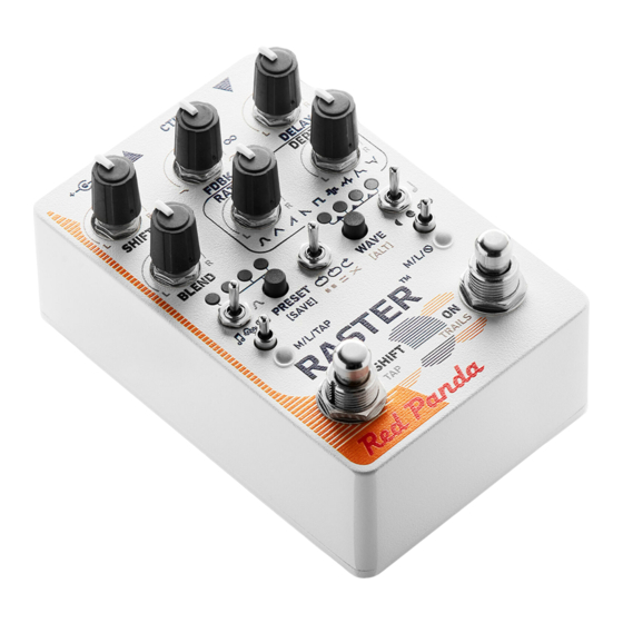
Page 7: Front Panel
Front Panel Alternate Controls 10 11 12 13 CTRL CTRL SHIFT FDBK DELAY SHIFTD FDBK ELAY RATE DEPTH RATE DEPTH BLEND BLEND PRESET WAVE PRESET WAVE [SAVE] [ALT] [SAVE] [ALT] M/L/TAP M/L/ M/L/TAP M/L/ SHIFT SHIFT TRAILS TRAILS 1. SHIFT footswitch. Hold down WAVE/[ALT] button to edit secondary 2. -
Page 8: Getting Started
Plugging In The Raster 2 requires an isolated power supply that can supply at least 250 mA of current (300+ mA preferred). Most problems are due to inadequate or overloaded power supplies. See our knowledge base for information about specific power supplies. - Page 9 Digital Delay Tricks Unlike analog delay pedals, the Raster 2 does not change the pitch as you turn the DELAY knob. Fast knob movements jump smoothly to the new delay time. Slow knob movements gradually change the delay time, with the Raster analyzing the signal to minimize glitches.
-
Page 10: Inputs And Outputs
Inputs and Outputs DC POWER Connect a 9V DC center negative power supply rated at 250 mA or higher. USB mini B connector for MIDI, web editor, and firmware updates. 1/4" TRS mono or stereo input. CTRL 1/4" TRS jack for expression pedal, remote, or MIDI. 1/4"... - Page 11 Bypass Mode Auto Uses analog or DSP bypass, depending on other configuration. (default) Dry signal and bypass passes through DSP. Our pedals use studio-quality A/D and D/A converters with low latency. This is a good choice in most situations. Analog Dry signal passes through DSP when effect is on, and buffered analog signal path in bypass.
-
Page 12: Raster 2 Controls
Raster 2 Controls Controls are identified by their front panel labels in BOLD. Alternate controls are labeled in gray, and are related to the primary (blue) control label. They are saved to presets and remembered when the pedal is turned off. Each each knob's alternate function is related to its primary function and the default setting is 12:00 (center). - Page 13 rewind what you just played, turn down the feedback and use reverse delay feedback mode. Trails Delay trails allow the repeats to decay naturally after the pedal has been switched to bypass. Global trails setting Echoes stop immediately when effect is turned off. Echoes decay naturally after effect is turned off.
- Page 14 [ALT]-DELAY adjusts the offset or ratio between the left and right delay. Turn the knob left or right to control which delay is heard first. Turning the control counter-clockwise from 12:00 will shorten the left delay time. Turning the control clockwise will shorten the right delay time. [ALT]-DELAY settings close to 12:00 will add a small time offset between delay channels (0-30 ms).
- Page 15 The FDBK control adjusts the delay line feedback (regeneration). Infinite repeats at approximately 3:00 (∞), with greater than unity feedback above that. Due to nonlinearity and filtering in the feedback path, the exact spot where self-oscillation occurs will depend on the input signal and tone control. Increasing the FDBK control beyond self-oscillation will add distortion.
- Page 16 presets and remembered when the pedal is off. You can set the feedback left/right balance control to its minimum or maximum value to disable feed- back for the right or left delays, respectively. With the series delay structure, for example, that allows you to put a slapback delay in front of a longer delay with feedback.
- Page 17 Shift Left/Right Balance [ALT]-SHIFT adjusts the shift left/right balance. In most shift modes, turning the control counter-clock- wise will cause the right channel to shift less, then no shift, then shift opposite the right channel at the minimum. Turning the control clockwise will keep the right shift constant while reducing, disabling, and then inverting the left delay shift.
- Page 18 Position (approx.) LEDs Right shift 5:00 ○○○○ ○○●● +1 octave If independent left/right shift is enabled, the LEDs will show the control position instead of the patterns above. Detune Detune mode smoothly shifts from a 4th down to a major third up, with emphasis on small pitch ratios. Small shifts created chorused or detuned sounds.
- Page 19 Harmonic A440 (Hz) Pitch Shift + perfect fifth Frequency Shift + 220 Hz 5th harmonic 2200 3300 2420 The shift left/right balance ([ALT]-SHIFT) control will keep the left (CCW) or right (CW) delay shift con- stant while reducing and then inverting the shift of the other delay. Turning the control counter-clock- wise will keep the left shift constant while reducing, disabling, and then inverting the right delay shift.
- Page 20 Modulation Controls Adjusts the modulation LFO frequency from approximately 0.05 - 10 Hz. The modulation waveform LED blinks at the LFO frequency (if MOD DEPTH is not off). When envelope or inverse envelope modulation is selected, this control will have no effect. The MOD PHASE L/R (ø) control adjusts the relative phase of the modulation between the left and right delay lines.
- Page 21 Delay time and modulation can be synchronized to tap tempo or MIDI timing clock. Modulation can be synchronized to tap tempo or MIDI clock using the editor or MIDI. Raster V1 Controls To use the Raster 2 like the Raster 1: Set the RATE and DEPTH controls to minimum (7:00). •...
-
Page 22: Control Input
Control Input The CTRL (control) input supports different methods of remotely controlling the pedal: • Expression pedal • Control voltage (CV) with 0-3.3V range • Tap Tempo • TRS MIDI in (tip active) • Remote switch To configure a expression pedal or remote switch, hold down the right footswitch while plugging it in. The pedal will detect which device is connected using the steps below. - Page 23 Control Voltage Control voltage input is configured the same way as an expression pedal. CV Range: 0-3.3V (with over/under-voltage protection) Tip: 0-3.3V input Ring: 3.3V output (with current limiting) Sleeve: ground The expression input has current limiting in case you use a TS cable, but it is preferable to use a 1/4” TRS cable with the ring unconnected.
- Page 24 Remote Modes Mode Switch Function LED Indication Preset 1 Blinks green when saved Double tap: manual settings Hold (4 sec): save Preset 2 Blinks green when saved Double tap: manual settings Hold (4 sec): save Preset 3 Blinks green when saved Double tap: manual settings Hold (4 sec): save Preset 4...
-
Page 25: Web Editor
Web Editor The web editor can be used to configure your pedal, access hidden parameters, and fine-tune presets. It is intended for "offline" configuration and editing. For live performance editing, we recommend using dedicated MIDI hardware or software and MIDI control change messages. Connect your pedal to a computer using a USB cable and go to the web editor URL using Chrome: https://www.redpandalab.com/content/apps/raster-editor/index.html Note the https in the URL. - Page 26 This tab also displays the installed firmware version and the input power supply (PSU) voltage. A low PSU voltage may indicate that the power supply is not able to provide enough current to properly power the pedal. Help The Show MIDI Devices button on the Help tab will display all of the MIDI devices accessible by your browser.
-
Page 27: Reset To Factory Defaults
Reset to Factory Defaults Use the following procedure to reset the Raster's configuration data to factory default settings. This will erase any advanced configuration and control port settings, but presets will not be affected. Note that this is rarely useful for troubleshooting problems with your pedal. 1. -
Page 28: Effects Design With The Raster 2
Effects Design With the Raster 2 The Raster 2 combines delay, modulation, pitch, phase, and frequency shifting (all in stereo). It is capa- ble of a wide range of delay-, pitch-, and amplitude-based effects. Some effects can be acheived multi- ple ways, with slightly different sounds. -
Page 29: Using Midi
Using MIDI Your pedal supports USB MIDI (in/out) and 1/4" TRS MIDI (input only). Every parameter (and more) is fully controllable, allowing you to synchronize the pedal with sequencers, integrate it with your DAW, and change presets on multiple pedals with one button during a performance. Even if you do not use MIDI directly, it is the underlying protocol for our web editor and pedalboard controllers. - Page 30 MIDI Continuous Controller Messages CC Num Destination Notes Expression pedal CTRL input Blend Blend L/R tilt Shift Shift L/R tilt Delay time Delay time L/R tilt Feedback Feedback L/R tilt Modulation rate Modulation phase L/R tilt Modulation depth Modulation depth L/R tilt Tone SHIFT/TAP footswitch Use gated mode to send 127 on...
- Page 31 CC Num Destination Notes 64-127 Remote tap (Receive only) Shift on/off 0-63 Shift off (Receive only) 64-127 Shift on Modulation waveform Sine Triangle Ramp up Ramp down Square Random step Random smooth Envelope Inverse envelope Modulation destination Wet amplitude (tremolo) Shift Delay time (default) Shift mode...
- Page 32 CC Num Destination Notes Right footswitch mode* Momentary Latch Mute output in bypass Shift link left/right channels Linked (tilt, default) Independent Feedback invert** 0-63 64-127 * indicates values that are remembered when pedal is turned off, but not saved in presets. •...
- Page 33 MIDI Timing Clock MIDI timing clock messages are used to synchronize multiple MIDI devices to a single clock transmitter. The clock is typically provided by a DAW in computer-based setups and a sequencer or drum machine in hardware-only setups. Dedicated MIDI clock generators are available for more complicated setups that need tight synchronization, and some devices can convert between MIDI clock, DIN sync, and taps.
- Page 34 MIDI real time messages are high-priority messages that can interrupt other MIDI messages to ensure the best possible syncronization timing. However, the accuracy of the clock depends on the transmit- ter and any devices it passes through. It is common to have +/-1 milliseconds of jitter, with is irregular timing due to individual clock ticks arriving too early or too late.
- Page 35 CC Value Note Division 16th note triplet Dotted 32nd note 32nd note 32nd note triplet Dotted 64th note 64th note 64th note triplet Dotted 128th note 128th note...
- Page 36 Raster. The basic format is the same for all messages: Byte (hex) Description System Exclusive (SysEx) Red Panda ID byte 1 Red Panda ID byte 2 Red Panda ID byte 3 Raster family ID Raster product ID...
- Page 37 Properties Firmware Version ID 1 ID 2 Data Bytes Data Firmware version: 0: Major 1: Minor 2: Patch 3: Release type (ascii) 4-7: Build number Returns the firmware version. Input voltage ID 1 ID 2 Data Bytes Data 100 * PSU voltage in Volts Returns the approximate input voltage.
- Page 38 MIDI Channel ID 1 ID 2 Data Bytes Data 00: channel 1 (default) 01: channel 2 0F: channel 16 Get or set MIDI channel. Save preset ID 1 ID 2 Data Bytes Data Preset location (MIDI program number) Save a preset to internal memory. Get / Set Parameter Value (high resolution) ID 1 ID 2...
-
Page 39: Support, Repairs, And Warranty
Support, Repairs, and Warranty Technical Support Please register your product at redpandalab.com/register within 30 days of purchase. For technical support, send your question via email to support@redpandalab.com or use the contact form on our web site. Be sure to include your serial number. We are a small company with limited re- sources for technical support, so it might take us a few days to reply. - Page 40 Product within thirty (30) days of receipt. You are solely responsible for the payment of shipping costs and expenses to ship the Product to Red Panda. Red Panda will pay the cost of ship- ping the repaired or replacement Product to you. If the Product is returned for service and/or repairs, Red Panda will complete the repairs within sixty (60) days of receipt and ship the Product back to you.
-
Page 41: Firmware Updates
Firmware Updates The Context's firmware can be updated via drag and drop using any Mac or PC. No driver or special soft- ware is required. To tell which version of firmware your pedal is running: 1. Hold down the PRESET (left) footswitch and connect power. 2. -
Page 42: Specifications
Specifications Maximum input level: +0.5 dBu (high gain) +5.2 dBu (default) +8 dBu (max with unity gain) +12 dBu (max with -3 dB pad) Frequency response: 20-20 kHz, +0/-0.5 dB Input impedance: 1 MΩ Output impedance: < 1 kΩ Bypass: analog buffered or DSP Power supply: 9V DC, center negative...
Need help?
Do you have a question about the RASTER 2 and is the answer not in the manual?
Questions and answers