Table of Contents
Advertisement
Quick Links
SECTION ONE: LSSM
SECTION TWO: LSSM
SECTION THREE: OPM1
SECTION FOUR: OPM1
SECTION FIVE: HFM1
SECTION SIX: VFF1
NORTH AMERICA
SWIFT TEST KIT
TRAINING MANUAL
TABLE OF CONTENTS
|
LASER LIGHT SOURCE
|
LASER LIGHT SOURCE
|
OPTICAL POWER METER
|
OPTICAL POWER METER
|
HANDHELD INSPECTION MICROSCOPE
|
VISUAL FAULT FINDER
uclswiftna.com
TEK-6
|
QUICK START GUIDE
|
TECHNICAL GUIDE
|
QUICK START GUIDE
|
REFERENCE & TEST GUIDE
|
QUICK START GUIDE
|
QUICK START GUIDE
Advertisement
Table of Contents

Related Manuals for UCL SWIFT TEK-6

Summary of Contents for UCL SWIFT TEK-6
- Page 1 NORTH AMERICA SWIFT TEST KIT TEK-6 TRAINING MANUAL TABLE OF CONTENTS SECTION ONE: LSSM LASER LIGHT SOURCE QUICK START GUIDE SECTION TWO: LSSM LASER LIGHT SOURCE TECHNICAL GUIDE SECTION THREE: OPM1 OPTICAL POWER METER QUICK START GUIDE SECTION FOUR: OPM1 OPTICAL POWER METER REFERENCE &...
- Page 2 NORTH AMERICA SECTION LSSM LASER LIGHT SOURCE QUICK START GUIDE...
-
Page 3: Quick Start
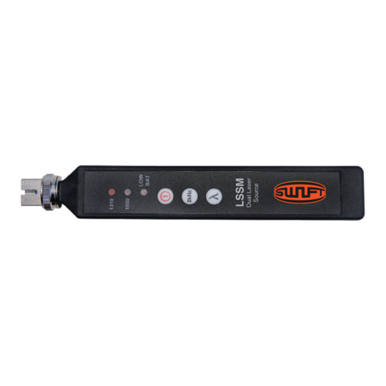
LSSM Laser Light Source - SM NORTH AMERICA Low Battery 2kHz Button QUICK START GUIDE Indicator Connector Adapter External Power Change Wavelength Port Button Power Button Wavelength Indicator INTRODUCTION The LSSM dual laser source is a singlemode test laser used for verifying the proper function of fiber optic networks. -
Page 4: Output Power
LSSM WARNING Read and understand all of the instructions and safety information in this manual before operating this tool. LASER HAZARD Please note that 1310nm and 1550nm wavelengths are not visible to the human eye. Do not look directly into the output port of the LSSM or directly into any fiber connector that may be live. Since the laser is invisible to the eye, the eye’s natural blink reflex is suppressed. - Page 5 LSSM OUTPUT PORT MAINTENANCE The LSSM utilizes a physical fiber connection at the output port. It ensures a steady power level for performing insertion loss tests. Ensure that any test jumpers are inspected and cleaned before plugging into the LSSM unit. If soiled or damaged connectors are inserted, they can cause damage to the LSSM output port and the unit may need to be repaired.
-
Page 6: Maintenance
LSSM TESTING NOTES Blue connectors (UPC) have a straight ferrule with a domed interface. Green connectors (APC) have an eight-degree angled ferrule with a domed interface. UPC and APC connectors are not compatible. NEVER connect UPC and APC connectors together, OR plug an APC connector into the LSSM unit. -
Page 7: Specifications
LSSM PSD1 BATTERY BYPASS SWIFT offers the PSD1 wall plug for users who wish to leave their LSSM turned on for long periods of time. This is a charger, but rather powers the unit from a wall outlet. SPECIFICATIONS DUAL SINGLEMODE LASER SOURCE Wavelength 1310nm &... - Page 8 LSSM CERTIFICATIONS This product conforms with health, safety, and environmental protection standards for products sold within the European Economic Area (EEA). This product was tested by an ISO 17025 accredited laboratory and complies with the following CE directives and standards listed below: DIRECTIVES: Electromagnetic Compatibilities (2014/30/EU) STANDARDS: EMC: EN 61326-1:2013 Industrial;...
- Page 9 NORTH AMERICA SECTION LSSM LASER LIGHT SOURCE TECHNICAL GUIDE...
- Page 10 The LSSM dual laser source provides stabilized optical power levels for accurate loss measurements on singlemode fiber systems. Technicians can utilize each of the wavelengths included in this light source to reference and test with UCL Swift’s optical power meters and gather measurements to meet international standards.
- Page 11 LSSM SPECIFICATIONS DUAL SINGLEMODE LASER SOURCE Wavelength 1310nm & 1550nm Output Power -5.0dBm ±0.05dB (1 hour) Output Stability ±0.03dB long-term (15 min warm-up) Spectral Width 5nm/5nm Optical Interface SC/FC/ST/LC interchangeable Tone Output 2kHz Laser Class Class 1 (FDA 21 CFR 1040.11) Power Push button toggle/auto-off Battery...
- Page 12 NORTH AMERICA SECTION THREE OPM1 OPTICAL POWER METER QUICK START GUIDE...
- Page 13 OPM1 Optical Power Meter NORTH AMERICA Save Button USB Button QUICK START GUIDE 2kHz Tone Button Indicator Low Battery Indicator Connector Adapter Power Button dB/dBm Measurement Button Mode Indicator LCD Screen Wavelength FEATURES Button The OPM1 comes with a 2.5mm universal adapter. Additional adapters CONNECTOR ADAPTER are available from SWIFT.
-
Page 14: Important Safety Information
OPM1 Hold the button to switch the OPM1 between the 850, 1300, 1310, 1490, 1550, 1611, and 1625nm wavelengths. Press the button once to WAVELENGTH BUTTON immediately display the current wavelength. The selected wavelength will briefly appear on-screen every 8 seconds. Press the button to toggle between dB and dBm modes. - Page 15 OPM1 FUNCTION TIPS AUDIBLE ALERTS The OPM1 emits an audible beep each time a major function is used. To disable most beeps, ensure that the unit is OFF. Press and hold the Save button, and turn the unit ON while holding the Save button. Perform the same procedure to turn the audible beeps back on.
-
Page 16: Data Streaming
The connector adapter interface should be kept covered and protected from contamination. Care must be taken to avoid objects that may damage the glass surface of the detector mount. If scratches or breaks occur on the surface, please contact UCL Swift NA for proper service. CALIBRATION All SWIFT brand products include a 2-year warranty. - Page 17 OPM1 SPECIFICATIONS OPTICAL POWER METER Detector Type -02: InGaAs/-04: Filtered InGaAs Measurement Range -02: +6 to -70dBm/-04: +23 to -45dBm Wavelength Range 850nm to 1650nm Selectable Wavelengths 850/1300/1310/1490/1550/1611/1625nm Resolution 0.01dB Absolute Accuracy ±0.25dB (23ºC +/- 2ºC at 0dBm) Optical Interface Universal 2.5mm (additional adapters available) Display Tone ID...
- Page 18 OPM1 CERTIFICATIONS This product conforms with health, safety, and environmental protection standards for products sold within the European Economic Area (EEA). This product was tested by an ISO 17025 accredited laboratory and complies with the following CE directives and standards listed below: DIRECTIVES: Electromagnetic Compatibilities (2014/30/EU) STANDARDS: EMC: EN 61326-1:2013 Industrial;...
- Page 19 NORTH AMERICA SECTION FOUR OPM1 OPTICAL POWER METER REFERENCE & TEST GUIDE...
- Page 20 OPM1 Optical Power Meter NORTH AMERICA REFERENCE & TEST GUIDE INTRODUCTION Performing a test for Insertion Loss (also commonly called dB Loss or Attenuation) on a fiber optic cable requires an Optical Power Meter (OPM) and an Optical Light Source (OLS). This document outlines the specific steps which must be taken with OPM1 optical power meter to perform insertion loss testing on a variety of fiber types and setups.
-
Page 21: Power Meter
Example 1: Singlemode Fiber, Po Example 1: Singlemode Fiber, Point-to-Po OPM1 Fiber Type Singlemode Fiber Type Singlemode EXAMPLE 1: SINGLEMODE FIBER, POINT-TO-POINT, 1 JUMPER Connectors Used Connectors Used Fiber Type Singlemode Test Jumper Setup Single Test Jumper Setup Single Connectors Used Test Jumper Setup Simplex jumper SC/LC OPM Used... -
Page 22: Setting Reference
Referencing Setup OPM1 Referencing Setup Referencing Setup Referencing Setup The connectors on the Test Jumper should be cleaned to appropriate standards. Use an inspection scope to verify fiber cleanliness. Plug the connectors on the Test Jumper into the RP 460 and DLS 355. The connectors on the Test Jumper should be cleaned to appropriate standards. - Page 23 Example 2: Singlemode Fiber, Po Example 1: Singlemode Fiber, Point-to-Po OPM1 Fiber Type Singlemode Fiber Type Singlemode EXAMPLE 2: SINGLEMODE FIBER, POINT-TO-POINT, 2 JUMPERS Connectors Used Connectors Used Fiber Type Singlemode Test Jumper Setup Double Test Jumper Setup Single Connectors Used Test Jumper Setup (2) Simplex jumpers: (1) SC/LC + (1) LC/LC OPM Used...
- Page 24 Referencing Setup OPM1 Referencing Setup Referencing Setup Referencing Setup The connectors on the Test Jumper should be cleaned to appropriate standards. Use an inspection Referencing Setup scope to verify fiber cleanliness. Plug the connectors on the Test Jumper into the RP 460 and DLS 355. The connectors on the Test Jumper should be cleaned to appropriate standards.
- Page 25 Example 3: Singlemode Fiber, Pa Example 1: Singlemode Fiber, Point-to-Po OPM1 Fiber Type Singlemode Fiber Type Singlemode EXAMPLE 3: SINGLEMODE FIBER, PAIRED, LOOPBACK JUMPER Connectors Used Connectors Used Fiber Type Singlemode Test Jumper Setup Loopback Test Jumper Setup Single Connectors Used Test Jumper Setup Loopback OPM Used...
- Page 26 OPM1 Referencing Setup Referencing Setup Referencing Setup Referencing Setup The connectors on the Test Jumper should be cleaned to appropriate standards. Use an inspection The connectors on the Test Jumper should be cleaned to appropriate standards. Use an inspection The connectors on the Test Jumper should be cleaned to appropriate standards. Use an inspection REFERENCING SETUP Referencing Setup The connectors on the Test Jumper and loopback should be cleaned to appropriate standards.
- Page 27 Example 4: Multimode Fiber, Po Example 1: Singlemode Fiber, Point-to-Po OPM1 Fiber Type Multimode Fiber Type Singlemode EXAMPLE 4: MULTIMODE FIBER, POINT-TO-POINT, 1 JUMPER Connectors Used Connectors Used Fiber Type Multimode Test Jumper Setup Single Test Jumper Setup Single Connectors Used Test Jumper Setup (1) Simplex SC/LC OPM Used...
- Page 28 OPM1 Referencing Setup Referencing Setup Referencing Setup Referencing Setup Referencing Setup The connectors on the Test Jumper should be cleaned to appropriate standards. Use an inspection The connectors on the Test Jumper should be cleaned to appropriate standards. Use an inspection The connectors on the Test Jumper and loopback should be cleaned to appropriate standards.
- Page 29 Example 5: Multimode Fiber, Pa Example 1: Singlemode Fiber, Point-to-Po OPM1 Fiber Type Multimode Fiber Type Singlemode EXAMPLE 5: MULTIMODE FIBER, PAIRED, LOOPBACK JUMPER Connectors Used Connectors Used Fiber Type Multimode Test Jumper Setup Loopback Test Jumper Setup Single Connectors Used Test Jumper Setup Loopback OPM Used...
- Page 30 OPM1 Referencing Setup Referencing Setup Referencing Setup Referencing Setup Referencing Setup The connectors on the Test Jumper and loopback should be cleaned to appropriate standards. Use The connectors on the Test Jumper should be cleaned to appropriate standards. Use an inspection The connectors on the Test Jumper and loopback should be cleaned to appropriate standards.
- Page 31 NORTH AMERICA SECTION FIVE HFM1 HANDHELD INSPECTION MICROSCOPE QUICK START GUIDE...
- Page 32 HFM1 Handheld 400x Handheld 400x Inspection Microscope Inspection Microscope NORTH AMERICA QUICK START GUIDE INTRODUCTION The HFM1 Handheld 400x Inspection Microscope is used to inspect fi ber terminations and provide the most critical view of fi ber end faces. This 400x handheld microscope shows scratches and contamination with its clear optical performance and integrated laser safety fi lters and is ideal for examining ferrule polish quality.
-
Page 33: Operation
HFM1 OPERATION Input the fiber into the fiber Inspect with the eyepiece and Adjust the focus control to find insert entrance. press on the on/off LED switch. the clearest viewing. (Illumination) INNER STRUCTURE NOTE The two settings on the handheld fiber microscope provide an excellent view of the ferrule end faces. - Page 34 NORTH AMERICA SECTION VFF1 VISUAL FAULT FINDER QUICK START GUIDE...
- Page 35 VFF1 Visual Fault Finder NORTH AMERICA QUICK START GUIDE INTRODUCTION The VFF1 Visual Fault Finder is a compact but powerful fi ber optic cable test tool used to locate sharp bends The VFF1 Visual Fault Finder is a compact but powerful fi ber optic cable test tool used to locate sharp bends and breaks in the jacket or bare fi ber.
- Page 36 VFF1 OPERATION Properly install batteries. Switch in Choose a continuous wave Compact and intelligent design middle for power off, switch output mode for steady fault assists in locating breakpoints up for CW output, switch down illumination or a flashing output of a fiber.
Need help?
Do you have a question about the TEK-6 and is the answer not in the manual?
Questions and answers