Table of Contents
Advertisement
Quick Links
EN
INSTRUCTIONS
FOR USE
UP-TO-DATE
INFORMATION
Online up-to-date
information on all devices.
DEVICE FOR
REMOTE CENTRAL CONTROL
AND MANAGEMENT OF ELECTRIC FENCE
Compatible
• fencee energy DUO RF EDX
• fencee power DUO RF PDX
• fencee Monitor MX10
PHONE
CONTROL
Control and monitor
through mobile application.
Electric fencing
ALARM
SIGNALLING
Immediate problem alert sent
to the phone and e-mail.
1
Advertisement
Table of Contents

Related Manuals for Fencee GW100


Summary of Contents for Fencee GW100
- Page 1 Electric fencing INSTRUCTIONS FOR USE DEVICE FOR REMOTE CENTRAL CONTROL AND MANAGEMENT OF ELECTRIC FENCE Compatible • fencee energy DUO RF EDX • fencee power DUO RF PDX • fencee Monitor MX10 UP-TO-DATE ALARM PHONE INFORMATION SIGNALLING CONTROL Online up-to-date...
-
Page 2: Table Of Contents
Thank you for purchasing this product FENCE WiFi GATEWAY GW100 of the company VNT electronics s.r.o. This device complies with the security regulations by the valid law same as for the appropriate EU (CE) regulation The device complies with the EU directive 2014/53/EC, Meets all requirements of General licence of the Czech telecommunications office by the general authorization n. -
Page 3: Important Recommendations
3. PACKAGE CONTENTS • FENCE WiFi GATEWAY GW100 • RF antenna • 14 V/1 A power supply adapter for mains connection • 9.6 V backup battery power supply •... -
Page 4: Introduction
4. INTRODUCTION · FENCE WiFi GATEWAY GW100 enables remote central monitoring and control of the energizers and monitors. Up to twelve independent energiuers or connected control devices, monitors MX10, may be controlled within the antenna range. The gateway gathers all information relating to the operation of all connected devices. -
Page 5: List Of Main Advantages
· Detailed display of parameters of each energizer and monitor · Settable alarm limit for each connected device · Mains supply + backup battery power supply · Option to connect external warning system (siren, light) Keep track with mobile application fencee Cloud More on page 30 WELL-ARRANGED LIST OF... -
Page 6: Gateway Installation And Fence Connection
• Not exposed to direct sunlight. • An electrical outlet (230V) is nearby. RF energizer Energizer External alarm with siren High voltage connection cable Gateway WiFi GW100 Earthing cable Conductor Monitor MX10 Anticorrosive earthing rod Line connector External RF antenna... - Page 7 CLOUD Gateway GW100 RF energizer Monitor MX10 Tensioner Gate IInsulators Insulator of gate Warning sign...
-
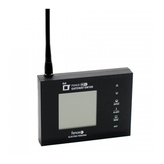
Page 8: Description Of The Device
7. DESCRIPTION OF THE DEVICE 7.1 Front side and operating touch keys The device can be operated using the touchpad shown. THE DEVICE CAN DISTINGUISH TWO TYPES OF PRESS: · Short press · Long press (more than 1 s) Graphic display with backlight Touch control panel Connector with relay, for external signaling Power adapter connector... - Page 9 KEYBOARD FUNCTION: Screen Functions Device selection in detailed and overview screen. Changing values in setup mode, navigating through menus. Short press - turns ON / turns OFF Overview Long press - switching power (50 / 100 %) and detailed screen It does not work on the monitor Short press - confirm, enter to another screen.
-
Page 10: Back Side
7.2 Back side Backup battery Socket for connecting the backup battery connector. -
Page 11: Ready To Use
8. READY TO USE Inserting backup battery 9.6 V backup battery power supply used in the event of mains power failure is able to supply the device for up to one day, however it depends on the device settings such as backlight or volume. -
Page 12: Device Manager - Pairing Device
Pairing is the process of linking communication between two devices. The gateway GW100 can pair up to twelve different devices. The device can be renamed individually. If all positions are occupied, it is not possible to start a new pairing! 9.1 Pairing new device - energizer... - Page 13 . Remote Pairing The gateway GW100 also enables remote pairing for energizers energy DUO RF EDX. This me- ans that you do not have to have a energizer directly at the gateway to be able to pair it. Pai- ring can be performed over long distances using a code.
-
Page 14: Pairing New Device - Monitor
9.2 Pairing new device - monitor To select pairing, press and hold 1. Use the arrows to move to Pairing and by press the key you will get to the Device Manager where you work with the device. 2. Switch the monitor to pairing mode: •... - Page 15 Optional designation: A - L • Device name: only a designation that is not yet used is offered. • Associated to: see explanation on page 16 monitor Subordination. 7. Editing - for entering press , by arrows choose marking and confirm 8.
-
Page 16: Subordinate Monitor To The Energizer
9.3. Subordinate monitor to the energizer If you place one or more monitors on a fence powered by a specific energizer, we recommend that these monitors be subordinated to the energizer. The main advantage is that if the energizer is intentionally switched off, no alarm is indicated on the monitors. -
Page 17: Editing Device Labels
9.4 Editing device labels Paired devices can be assigned a distinguishing sign. Each device can only be assigned a name that is not yet in use. To select editing, press and hold 1. Use the arrows to move to Pairing and by press the key you will get to the Device manager where you work with the device. -
Page 18: Overview Screen
10. OVERVIEW SCREEN The screen provides an immediate overview of all connected devices. Type of device GX or MX marking indicates a generator device (energizer) · indicates a monitor device · 1 - 12 A - L · X indicates optional name to distinguish between energizers or monitors ·... - Page 19 Energizer state and its power • power 0% - energizer is off, the device communicates (in standby mode) see energizer G3 • power 50% - the energizer is switched on and set to half power see energizer G2 • power 100% - the energizer is turned on and set to full power see energizer G1 •...
-
Page 20: Detailed Screen - Energizer And Monitor
11. DETAILED SCREEN - ENERGIZER AND MONITOR Detailed screen is used to show all the possible information about concrete device. The name of device (possibility to change by user) There is displayed MAC address of the connected device under the name. Energizer state and its power This status is not indicated for the monitor. -
Page 21: Menu - Setting Of The Device
12. MENU - SETTING OF THE DEVICE To enter the menu, press and hold the key from an overview or detailed screen. Use the arrows to move the cursor and you can get inside by short press of key To exit the menu, press shortly the key 12.1 Sound settings - Sound setting gateway. -
Page 22: Display Settings
12.2 Display settings - Contrast setting (-50 to +50); negative values invert the display colours into so-called Night Mode Backlight intensity setting 0% to 100% is active only if backlighting is enabled (refer to Backlight) Enabling the display backlighting On or Off Setting the time for the backlight to turn off automatically from the last key press;... - Page 23 » The user has the option to set up signal transmission control between the gateway and paired devices at set intervals. 60 min is set for all devices by default. The user is able to set shorter intervals in order to be notified of a signal failure earlier. Interval options: 15 min •...
- Page 24 Cloud application and thus to the mobile application and web browser. This option changes the current gateway MAC address. This function will be used particularly when the GW100 gateway is bought from another user. Changing the MAC address will ensure that all previously connected devices are disconnected from the gateway.
- Page 25 Setting procedure: Selection of pairing is called up by holding down By using select Advanced Set up; press By using select Generate new MAC and press Enter pin to gateway screen appears. By using move to the individual positions one by one, press and by using the correct character;...
-
Page 26: Device Information
13. Wi-Fi CONNECTION Mobile phone with Internet connection that is capable reading the QR code with the camera or with application for reading QR codes is required. GW100 installation site must have good Wi-Fi cover. 1. Wi-Fi module settings By holding down displayed on the overview or detail screen selection appears. - Page 27 This is GW100 main screen ready for Wi-Fi connection. Using select Configure WiFi and press 4. GW100 will display Activating config mode message and the QR code will appear with designation WiFi connect. Scan the displayed QR Code with your mobile phone. Code may also be scanned here.
- Page 28 6. Select the appropriate Wi-Fi in the web browser and login by entering the correct password. 7. If all is correct, the GW100 will close the QR code window within approximately 15 seconds. The SSID line will display the name of the connected Wi-Fi and the second line will display...
- Page 29 Your device may now be activated and managed on the web browser or in the mobile applica- tion. For this, MAC address and Pin, unique codes for your GW100 device, are required. These may be found in the package contents (label on the back of this manual and in the product box).
-
Page 30: Fencee Cloud Application
14. fencee Cloud APPLICATION • Keeping track of and check over the devices connected to GW100 • Device may be turn on and off remotely as well as changing power output • Option to set voltage limit when the alarm is triggered •... -
Page 31: Error Reporting, Signaling, Deleting
15. ERROR REPORTING, SIGNALING, DELETING Each connected device reports its alarms directly to the gateway. These errors may be with the following signaling: Low battery • Battery connected to an energizer - the battery symbol flashes when the voltage drops below 12 V. -
Page 32: Reset To Factory Settings
16. RESET TO FACTORY SETTINGS Resetting includes: • Deleting all paired devices. • Formating empty positions. • Resetting the display contrast and backlight settings. • Resetting the sound settings. If necessary, reset the gateway to the factory settings follow those instructions: To select resetting, press and hold 1. -
Page 33: Hole Drilling Template
18. HOLE DRILLING TEMPLATE... -
Page 35: Guarantee
19. GUARANTEE In addition to a guarantee requested by law, we provide you with a guarantee in accordance with below listed conditions: • Guarantee period begins on the day of its purchase. Guarantee claims are acknowledged explicitly pursuant to submission of bill or cash voucher. Guarantee repair is free of charge, or we reserve the right to deliver a device of the same value. - Page 36 06052021 Stamp and signature of seller: MAC + PIN Electric fencing VNT electronics s.r.o. Dvorska 605, 563 01 Lanskroun, Czech Republic info@fencee.eu fencee Cloud +420 730 893 828 Free app Servis: +420 730 893 827 fencee.cz fenceeczech www.fencee.eu www.fenceefarm.com www.fenceecloud.com...
Need help?
Do you have a question about the GW100 and is the answer not in the manual?
Questions and answers