Table of Contents
Advertisement
Quick Links
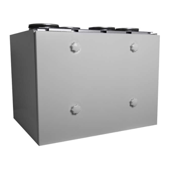
AIR EXCHANGE EQUIPMENT
INSTALLATION AND USER
MANUAL
THE QUALITY GOALS OF AIR CONDITIONING COME TRUE
WITH THE RECOVERY SYSTEM
TALTERI removes used air from interior and brings in fresh air.
Humidity and impurities are exhausted through thermal recovery
unit that heats the filtered ambient air cost-effectively. The fresh
warm air is channelled draught-free and noise-free into the
premises in necessary quantities.
ENSURE THE QUALITY OF AIR EXCHANGE!
DEEKAX Air Oy
R
TALTERI
DIVK-290 DEMA
QUALITY TESTED
Patruunapolku 4
79100 LEPPÄVIRTA
Puh. 0207 912550
www.deekaxair.fi
Advertisement
Table of Contents

Subscribe to Our Youtube Channel
Related Manuals for Deekax TALTERI DIVK-290 DEMA

Summary of Contents for Deekax TALTERI DIVK-290 DEMA
- Page 1 The fresh warm air is channelled draught-free and noise-free into the premises in necessary quantities. ENSURE THE QUALITY OF AIR EXCHANGE! Patruunapolku 4 Puh. 0207 912550 DEEKAX Air Oy 79100 LEPPÄVIRTA www.deekaxair.fi...
- Page 2 MACHINE PARTS AND TECHNICAL INFORMATION 1 Exhaust air....125mm 2 Outdoor air....125mm 3 Extract air....(2x) 125mm 4 Supply air ....(2x) 125 mm 5 Main switch 6 Supply fan EC 118 W 7 Extract fan EC 118 W 8 Heat exhanger 9 Postheater 1000 W 10 Extract/supply air filter (G4) ISO Coarse>75%...
- Page 3 INSTALLING THE CHANNELLING The channels for exhaust air and incoming air should be installed, if possible, in a warm space below the vapour barrier to suspended ceilings or casing. The vapour barrier remains intact and the channels do not need heat insulation.
- Page 4 TALTERI DIVK-290 INSTALLATION The air exchange unit is meant f or warm inner f acilities. Suitable installation spots are, among others, of f ice, dressing or household f acilities and technical or warm storages. In case the temperature of the installation location is lower than room temperature, the f actory settings of the appliance must be changed to obtain f aultless f unctioning.
- Page 5 DIVK-290 INSTALLATION TO A SUSPENDED CEILING The ceiling-mounting plate is attached to the ceiling with M8 thread bars (not included in the delivery). M8 THREADED BAR BACKUP NUT THE TOP SURFACE OF THE RUBBER SILENCER MOUNTING PLATE EDGING IS WASHER INSTALLED AT THE LEVEL OF THE CEILING SURFACE.
-
Page 6: Electrical Connections
CONSENSATE WATER DIVK heat exchanger units have a water trap built from a condensate hose located under the base plate (Fig 1). If a condensate trap outside the machine is used, the machine's own water trap must be removed and care Door of the unit TALTERI must be taken to ensure that the condensate... -
Page 7: Switch On/Off
DIVK-290 DEMA EXTRACT SUPPLY SWITCH ON-OFF Triac POST- HEATER A/D+ B/D- O O O ON OFF BIAS B O O O ON OFF Term O O O ON OFF BIAS A Control board POST- PRE- CONTROL HEATER HEATER PANEL OVERPRESSURE/ OUT-OF HOUSE/ TEHOSTUS CO2/%RH1... - Page 8 THE INTRODUCTION OF A VENTILATION UNIT BEFORE OPERATING YOUR AIR EXCHANGE SYSTEM, USAGE AND CORRECT LEVEL OF AIR EXCHANGE The air exchange level is regulated by changing the MAKE SURE THAT: working speed of the air impeller from the operating panel. - There are no loose objects within the unit or the air impeller;...
-
Page 9: Service Menu
INTRODUCTION OF THE AHU CONTROL PANEL Settings are applied via the service menu SERVICE MENU Note: swipe right at SETTINGS the top of the screen 0-10V external control (0-10V hood,remote monitoring) select the deployment SENSOR 1 "EXT" or SENSOR 2 "EXT" External control controls the basic speed , replaces the fan speed set in the menu. -
Page 10: Touch Screen Buttons
OPERATING PANEL USER INSTRUCTION MAIN DISPLAY AND ADJUSTMENT OF BLOWING SPEED CLOCK THE DISPLAY ALSO SHOWS POSSIBLE INCREASED EFFICIENCY AND MALFUNCTIONS EDIT Touch screen buttons: HUMIDITY AND CARBON DIOXIDE VALUE Fan speed adjustment 1..5 IF SENSORS ARE INSTALLED (accessory equipment) TEMPERATURE DISPLAY FOR Out-of-house mode TEMPERATURE OFOUTSIDE AIR,... -
Page 11: Setup Menu
SETUP MENU SETTINGS Fan speed adjustment 1..5 Touch screen buttons: Fan speed adjustment 1..5 Out-of-house mode Fireplace switch (pressure compensation) Boosting The button can be used to browse menu upwards and change settings. Maintenance interval and reset The button can be used to browse menu downwards and change setting value. -
Page 12: Maintenance Menu
MAINTENANCE MENU SETTINGS Touch screen buttons: Fan speed adjustment 1..5 Out-of-house mode Extended time(office mode) SWIPE RIGHT AT THE TOP OF THE SCREEN Boosting HOME overpressure activated The button can be used to browse menu upwards and change settings. OFFICE continuation time activated The button can be used to browse menu downwards and change setting value. - Page 13 Regulation of Inlet Air and Pre-heating value The value of pre-heating should be regulated to be approx 5c higher than the Freeze-alert settings -10…10 limit of cold exhaust air Overpressure duration specification 0 and 5...20min. In 0 position with different switch pre-data. Overpressure limit regulation 1...4 Anti-freeze appliance’s control (inlet air impeller higher than outlet air impeller)
-
Page 14: Operational Description
OPERATIONAL DESCRIPTION 1. Operating panel The operation is directed according to settings inserted by the user or installer/manufacturer through the operating panel as well as according to temperature sensors and set periods. The operating panel returns from processing state to basic state 2 minutes after the last button pressing. The return time from normal position is 2 minutes. -
Page 15: Setting The Temperature
3.7. Office mode The installer can select the office mode from the maintenance menu – this is useful in case the air exchange system is installed into an office where activities take place mostly during daytime. The speeds are controlled by the weekly clock. The mode is equipped with continuation switch that enables persons who remain in the office for longer to prolong the functioning of the appliance by set interval. - Page 16 The heat recovery cell in the summer position, the bypass plate is turned winter position in the front of the cell, the outdoor air passes behind the heat recovery cell. DEEKAX Air Oy Patruunapolku 4 Puh. 0207 912550 79100 LEPPÄVIRTA www.deekaxair.fi...
Need help?
Do you have a question about the TALTERI DIVK-290 DEMA and is the answer not in the manual?
Questions and answers