Table of Contents
Advertisement
Quick Links
Universal Transmitter (UT-15SL)
Universal Transmitter monitors the opening/closing of specified device that is connected to it. If any alarm is triggered by the
connected device, the Universal Transmitter transmits the alarm signal to Control Panel to notify users of an alarm event.
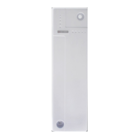
Universal Transmitter design consists of a cover and base. The cover contains all electronics and the base provides a means
for fixing the device.
The Universal Transmitter includes two models according to availability of tamper switch.
UT-15SL-F1: Tamper switch available
UT-15SL-NT-F1: Tamper switch removed
P
a
r
t
s
I
d
e
n
t
i
f
i
c
a
t
i
o
n
P
a
r
t
s
I
d
e
n
t
i
f
i
c
a
t
i
o
1. LED indicator a.k.a. Learn / Test button
2. Mounting Holes
Used to fixed and screw the Universal Transmitter directly onto
the Door Frame or Wall, covered by white caps.
3. Tamper Switch
Provides tamper protection against unauthorized device opening
and/or removal from mounting surface.
4. Battery Insulator
5. Fixing Screw
Screw used to secure the top and bottom case of the Universal
Transmitter.
6. Extension Terminal 1
Used for Door Contact, IR, Smoke Detector or Panic Button connection
7. Extension Terminal 2
Used for Roller shutter connection
8. DIP Switch
SW1
ON
OFF
SW2
ON
OFF
SW3
ON
OFF
SW4
ON
OFF
SW5
ON
OFF
SW6
ON
OFF
SW7
ON
OFF
SW8
n
Terminal 1 Type = Door Contact
Enable (Default)
Disable
Terminal 1 Type = IR
Enable
Disable (Default)
Terminal 1 Type = Smoke Detector
Enable
Disable (Default)
Terminal 1 Type = Panic Button
Enable
Disable (Default)
Supervision
Enable (Default)
Disable
CON4 NO/NC
Normal open
Normal close (Default)
Roller shutter Activation
8 pulse / 10sec
5 pulse / 10sec (Default)
Reserved
1
Advertisement
Table of Contents

Related Manuals for Climax Technology UT-15SL

Summary of Contents for Climax Technology UT-15SL
- Page 1 Universal Transmitter design consists of a cover and base. The cover contains all electronics and the base provides a means for fixing the device. The Universal Transmitter includes two models according to availability of tamper switch. UT-15SL-F1: Tamper switch available UT-15SL-NT-F1: Tamper switch removed ...
- Page 2 < > < > After you have set one function by sliding the DIP switch, you have to press Test Button to confirm the setting. Only 1 switch of Dip Switch 1~4 can be set to ON position at a time. ...
- Page 3 The Extension Terminal 1 of Universal Transmitter can be connected to a device to form a NO or NC loop with the device. When the device is activated, the Universal Transmitter will transmit signal accordingly CONNECTION TO EXTENSION TERMINAL: Step 1: Open the cover by loosening the fixing screw..
- Page 4 Federal Communication Commission Interference Statement This equipment has been tested and found to comply with the limits for a Class B digital device, pursuant to Part 15 of the FCC Rules. These limits are designed to provide reasonable protection against harmful interference in a residential installation.
Need help?
Do you have a question about the UT-15SL and is the answer not in the manual?
Questions and answers