Table of Contents
Advertisement
Preface.......................................................... 1
A.
Product Description
1. Product Usage............................... 2
2. Products Features......................... 2
3. Operation Principle........................2
4. Main Components......................... 3
B.
Security
1. Preparation..................................... 4
2. Notice for Security......................... 4
3. Operating Environment................ 4
C.
Carrying &Storage
1. With Carton Packing..................... 5
2. Storage for Short Time..............5
3. Storage for Long Time..............5
4. Restart after Storage.....................5
D.
Installation
1. Prerequisite for Installation.......... 6
2. Environment for Installation......... 6
3. Filling Oil......................................... 6
4. Connecting Electricity................... 8
E.
Start & Commissioning
1. Power on.......................................10
2. Standard Operation.....................11
3. Optimal Packing.......................... 11
F.
Standard Operation & Parameter
Setting
1. Control Panel............................... 12
2. Parameter Setting....................... 13
3. Optimal Parameter......................14
4. Packing Liquid Products............ 15
Program's Cycle.......................... 15
CONTENT
2. Vacuum Pump Maintenance........... 17
4. Replacing Filter..........................20
6. Replacing Silicon Strip..................... 2 3
7. Replacing Sealing Rubber...............2 3
8. Replacing Fuse..........................23
5. Error Code.........................................2 7
I.
3. B r e a k d o w n D r a w i n g o f H u l l &
4. B r e a k d o w n Dr a w i n g of Se a l i n g
5. Breakdown Drawing of Air Chamber
Electric Circuit Diagram..................34
Gas Circuit Diagram.......................35
Wire..................................................... 2 1
Body................................................... 2 5
Pump.................................................. 2 6
Valve...................................................2 6
Device................................................ 2 7
.............................................................2 8
Chamber............................................ 2 9
Bottom-plate.............................30
Epoxy Plate Assembly................32
Assembly.................................33
Advertisement
Table of Contents

Related Manuals for HUALIAN HVC-260T/1A


Summary of Contents for HUALIAN HVC-260T/1A
-
Page 1: Table Of Contents
CONTENT Preface............1 1. Standard Maintenance Schedule... 17 2. Vacuum Pump Maintenance... 17 Product Description 1. Product Usage....... 2 3. Special Oil for Vacuum Pump…..19 2. Products Features......2 4. Replacing Filter……………………..20 3. Operation Principle......2 5. Replacing Teflon Cloth & Heating 4. -
Page 2: Preface
Preface Thank you very much for your choice of our HVC-260T/1A Table-style Vacuum Packaging Machine! The content of this instruction is as following: Product Description Notice for Security Carrying & Storage Installation & Commissioning Operating Guide ... -
Page 3: Product Usage
Product Description 1. Product Usage HVC-260T/1A Table-style Vacuum Packaging Machine possesses the advantages of superior function, easy operation, simple maintenance, wide application etc. It applies to the soft packing material such as composite film or aluminum-plastic composite film and so on. It can pack grain, food, fruit, seed, medicine, chemical product, electronic product, precision instrument and meter, rare expensive metal etc, that in solid, liquid, powder or paste shape. -
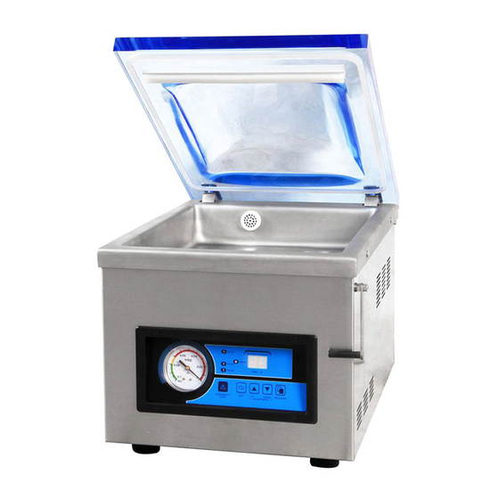
Page 4: Main Components
4. Main Components Components Name Remark Hull Stainless steel Vacuum chamber Stainless steel Vacuum lid Organic glass Silicon strip Sealing rubber Heating plate Air hole Power switch Control panel Nameplate Oil-level indicator Power socket... -
Page 5: Preparation
Fuse tube Fuse tube base B. Security 1. Preparation: This instruction is a detailed description of the Carrying, Storage, Installation, Startup, Operating condition, Maintenance, troubles & solutions and Repairing. It is recommended that the machine be installed by trained professional worker. Please do abide by the maintenance instruction. -
Page 6: With Carton Packing
Please choose the special vacuum pump oil in the food industry field if this machine is used for food industry. C. Carrying & storage 1. With Carton Packing If the machine is packed by carton with expanded gasket, Remove the expanded gasket from the carton. ... -
Page 7: Environment For Installation
D. Installation Please read this instruction carefully and understand it thoroughly before installation, to understand how to install, start up, maintain & operate. The manufacturer is irresponsible for any problems caused by not complying with this instruction. Any problems, please contact the manufacturer or distributor. 1. - Page 8 Note: The vacuum pump should be transported without oil. PAY ATTENTION! DAMAGE! Filling the oil to the vacuum pump through other position of the pump may damage the vacuum pump. The oil should be filled through the oil filler hole. TAKE CARE! SCALD! The oil tank is full with high-temperature and high-pressure oil mist.
-
Page 9: Connecting Electricity
Note: Please choose the special vacuum pump oil in the food industry field if this machine is used for food industry. 4. Connecting Electricity DANGEROUS! ELECTRIC SHOCK! Please make sure all the sockets have protective ground wire. TAKE CARE! Unmatched power will damage the machine. Please check the power parameter of the power referring to the name plate on the machine. - Page 10 TAKE CARE! DAMAGE! The incorrect rotation direction of the vacuum pump motor will damage the vacuum pump in even a short time. Please make sure the rotation direction is correct before startup. For the vacuum pump equipped with three-phase motor: Check the rotation direction of the vacuum pump according to the instructive mark.
-
Page 11: Power On
Don’t pack the goods that may be damaged when vacuuming or after vacuuming with this machine. If you have any question about the operation and the function that haven’t stated in this manual, please contact the manufacturer or distributor If the machine is running irregularly or makes strange noise, please turn off the power ... -
Page 12: Standard Operation
indicates the machine is in the standby state and it can be used. 2. Standard Operation □□ Turn on the power switch to startup and the monitor shows “ ”. Please adopt the composite bag suitable for vacuum packing and the bags should be ... -
Page 13: Control Panel
Standard Operation & Parameter Setting 1. Control Panel Figure Name Remarks Shows the state of the functions during the working; the numbers will diminish. Shows numbers of the parameter value of the selected Monitor function. Shows “□ □”for standby state Shows “E d”... -
Page 14: Parameter Setting
Working The indicator lights (in red) during the working period. indicator The corresponding indicator will light when one function is executed during the working period. Function When pressing the Function Selecting button to choose indicator one function, the corresponding indicator will light (in red). -
Page 15: Optimal Parameter
When function selected, Shows the set corresponding indicator lights (in red). Four value of the functions are respectively vacuuming time, selected gas-filling time (If any), sealing time, and cooling function. time. Press once to increase or decrease one unit of the selected function time. -
Page 16: Packing Liquid Products
The sealing function parameter influences the sealing quality greatly; the temperature should be adjusted slowly from low to high. The cooling time can be set between 1~3 seconds according to the thickness of the bags. 4. Packing Liquid Products The machine is suitable to pack liquid products, such as soup and sauce. -
Page 17: Maintenance
The pointer of the vacuum gauge keeps stay. The deflating begins as soon as the cooling is completed. The air comes into the chamber and the pressure inside the chamber is Deflating equal to the outside. The vacuum lid will open automatically. Monitor: shows “□... -
Page 18: Standard Maintenance Schedule
The machine works at most 8 hours in a day. The manufacturer is irresponsible if the user prolongs the working hour of the machine without consulting and damage the machine. If the machine is damaged or in problem as the user does not follow the instruction in ... - Page 19 There is no vacuum pump oil of the newly delivered machine. Please fill the oil for its first use. Check the color of the vacuum pump oil The vacuum pump oil is bright and clear without any foam or muddle. If there are white materials after precipitation, it indicates there are foreign materials in the oil.
-
Page 20: Special Oil For Vacuum Pump
Filling oil: TAKE CARE! DAMAGE! Correct oil type and quantity is essential to the vacuum pump. Incorrect vacuum pump oil or overfilled oil will damage the vacuum pump. The newly delivered machine should be filled with oil. Fill the oil after the oil-draining or when the oil level is low. ... -
Page 21: Replacing Filter
Replacing Filter TAKE CARE! POLLUTION! The polluted filter should be disposed separately from other wastes according to the regulation. There are one or several filters in the vacuum pump, which is used to absorb and filter the oil mist. The filter will turn wet (saturated) and need replacement. The machine can’t reach to the maximum vacuum level if the filter is saturated. -
Page 22: Replacing Teflon Cloth & Heating Wire
5. Replacing Teflon Cloth & Heating Wire Take care!Scald! The temperature of heating plate can reach higher than 200 ℃ when heating. Even after cooling, the surface of heating plate is still with high temperature. The sealing quality, to some extent, depends on the maintenance of heating plate and silicon strip. - Page 23 Replacing Teflon cloth or heating wire: Take off the heating plate Remove the Teflon cloth on the top face of heating plate If only need to replace the Teflon cloth, use a clean cloth to wipe the lipa and residual adhesive on the heating plate.
-
Page 24: Replacing Silicon Strip
6. Replacing Silicon Strip Check weekly whether the silicon strip is coarse. Replace the silicon strip once it is not flat. The average maintenance cycle of the silicon is at least once every 6 months. The silicon strip is blocked in the silicon strip support and it can be removed directly ... - Page 25 Replacing fuse for main circuit Main circuit fuse is placed in power socket. Unplug the power cord. Pull out the fuse base Take out the damaged fuse from the fuse base. install the new fuse into the fuse base. ...
-
Page 26: Troubles & Solutions
H. Troubles & Solutions Troubles & Solutions of Machine Body Troubles Reasons Solutions Put the power plug into the No connection of the power supply. The machine power socket. doesn’t work Replace fuse (same and the control The fuse of the main circuit burns out. specification). -
Page 27: Troubles & Solutions Of Vacuum Pump
Check whether the pressure gauge secondary pressure Incorrect setting of the filling pressure. atmospheric pressure (1-ATM). Warning! The compound gas can’t be higher than 1-ATM anytime. Normal vacuum Poor reposition of the heating plate. Repair the heating plate to level, but The distance between the heating make reposition... -
Page 28: Troubles & Solutions Of Sealing Device
4. Troubles & Solutions of Sealing Device Troubles Reasons Solutions Set an appropriate Heating temperature is not set heating temperature Shorten/prolong the sealing Too long/short sealing time time Sealing before the vacuum degree is Check the vacuum degree to achieved. be not higher than 0.6mpa. -
Page 29: Breakdown Drawings
can’t finish automatically. Solution: Replace or repair the approaching switch. Note: The approaching switch is in correct position, if there is signal in approaching switch and the machine startups, when close the vacuum lid in the position where its front-end is 10~20mm distance from vacuum chamber. -
Page 30: Br E Ak D Ow N Dr A W In G Of Va Cu U M
Breakdown Drawing of Vacuum Chamber Code Name Unit Remark Vacuum chamber assembly Epoxy plate assembly Air chamber sealing ring Air chamber assembly Tension spring adjusting pole Damping roller Damping roller axle Joint bearing Right door-hinge pit Door-hinge pin Right damping plate assembly Tension spring for opening lid M6 cylinder-head inner-hexagon screw GB/T70.1... - Page 31 Breakdown Drawing of Hull & Bottom-plate Code Name Unit Remark Hull M6 cylinder-head inner-hexagon screw GB/T70.1 Vacuum lid hook Circuit board Control panel box (PC material) Control panel cover (PVC material)
- Page 32 Vacuum gauge M4 screw Finger-protected switch holder Finger-protected switch Relay cushion Small relay Pin seat Combined solenoid valve Fixing support Support pole spring Control transformer Sealing transformer AC contactor Filter connector II Filter fixing support Filter Filter connector I Support pole Socket fixing support Power socket Fuse tube...
-
Page 33: Assembly
Breakdown Drawing of Sealing Epoxy Plate Assembly Code Name Unit Remark Teflon cloth 275×60(mm) 550×5(mm) Nickel chromium strip (heating wire) Pressure sensitive adhesive tape 275×19(mm) Heating wire copper cushion Epoxy plate M4 cross-sunk screw GB/T 819.1 fixing block for epoxy plate guiding pillar M6 Inner-hexagon flat-head screw GB/T 78 Heating wire copper presser... - Page 34 Breakdown Drawing of Air Chamber Assembly Code Name Unit Remark M5 nut air chamber Sealing pillar spring copper pillar airbag top plate airbag rubber plate air chamber cover M5 half circle-head screw O-type sealing ring air chamber connector...
-
Page 35: Electric Circuit Diagram
Electric Circuit Diagram... -
Page 36: Gas Circuit Diagram
Gas Circuit Diagram...
Need help?
Do you have a question about the HVC-260T/1A and is the answer not in the manual?
Questions and answers