Table of Contents
Advertisement
Quick Links
Documents are only to be used and distributed completely and unchanged. It is strictly the users´ responsibility to check carefully
the validity of this document with respect to his product. manual-no.: 999073 / 15/12/2009
page 1 of 51
Technology for Vacuum Systems
Instructions for use
Chemistry pumping units with speed control
MD 8C VARIO
MV 10C VARIO
PC 2008 VARIO
PC 2010 VARIO
PC 2012 VARIO
Advertisement
Table of Contents

Related Manuals for vacuubrand MD 8C VARIO


Summary of Contents for vacuubrand MD 8C VARIO
- Page 1 1 of 51 Technology for Vacuum Systems Instructions for use MD 8C VARIO MV 10C VARIO PC 2008 VARIO PC 2010 VARIO PC 2012 VARIO Chemistry pumping units with speed control Documents are only to be used and distributed completely and unchanged. It is strictly the users´ responsibility to check carefully...
- Page 2 2 of 51 Dear customer, Your VACUUBRAND diaphragm pump shall support you at your work for a long time without any trouble and with full load output. Thanks to our large practical experience we attained much information how you could add to an efficient application and to personal safety.
-
Page 3: Table Of Contents
page 3 of 51 Contents Safety information! ....................4 Technical data ......................8 Description ......................12 Notes on operation ....................14 General view basic setups ..................19 Working with the controller ..................20 General view basic setup ”vacuum control” ............23 Basic setup vacuum control................... -
Page 4: Safety Information
Attention: Make sure that a ground wire connection is established before the equipment is connected to mains supply! ➨ The pumping units MD 8C VARIO, MV 10C VARIO, PC 2008 VARIO, PC 2010 and PC 2012 VARIO are devices with double-pole cutoff and a symmetric capacitive circuit. - Page 5 page 5 of 51 ☞ Provide a firm level platform for the equipment and check that the system to be evacuated is mechanically stable and that all fittings are secure. Attention: Flexible elements tend to shrink when evacuated. Due to the high compression ratio of the pumps, pressure at the outlet port might be generated being higher than the max.
- Page 6 page 6 of 51 In case of overload the motor is shut down by a thermal cutout in the winding. ☞ Manual reset is necessary. Switch off the pump or isolate the equipment from mains. Wait approx. five minutes before restarting the pump. ☞...
- Page 7 page 7 of 51 ➨ Isolate equipment from mains and wait two minutes before starting mainte- nance to allow the capacitors to discharge. ☞ Ensure that the pump cannot be operated accidentally. Never operate the pump if covers or other parts of the pump are disassembled. Never operate a defec- tive or damaged pump.
-
Page 8: Technical Data
The pump achieves its ultimate pumping speed and ultimate vacuum only at operating temperature and at 60 Hz (after approx. 15 min.) VACUUBRAND pumps of type MD 8C VARIO / MV 10C VARIO / PC 2008 VARIO / PC 2010 VARIO / PC 2012 VARIO are pumps for professional use at vacuum technical systems connected to low-voltage power supply systems of trade, research or industry. - Page 9 page 9 of 51 i t i c t i ) r r ) r r " ( " y l l < ) r r b i l c i f < / r r ) r r ° 0 The actual vacuum control range in your special application might be reduced due to ultimate vacuum of the pump, quantity of gas occurring etc.
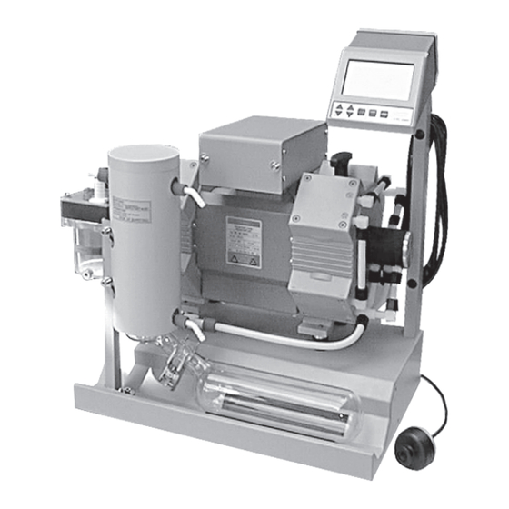
- Page 10 10 of 51 MD 8C VARIO handle gas ballast valve outlet rating plate inlet pump MD 8C VARIO with frequency converter pressure transducer VSK 5 controller CVC 2000 MV 10C VARIO handle gas ballast valve outlet rating plate inlet...
- Page 11 (hose nozzle 10 mm) rating plate inlet (vacuum connection) cooling water outlet (hose nozzle 6 mm) separator at the inlet pump MD 8C VARIO cooling water inlet with frequency (hose nozzle 6 mm) converter overpressure safety relief device at the collecting flask for...
-
Page 12: Description
page 12 of 51 Description The controller can be adapted to the specific application by choosing another basic setup than ”Vacuum control” (factory-set), see section ”General view basic set- ups”. The status of the controller respectively of the connected accessories is displayed by corresponding symbols on the LCD. - Page 13 page 13 of 51 Keys • setting frequency • operating venting valve (only if • setting time for switch-off (only VACUU•LAN) valve is connected and prese- • switching (toggling) in setups lected) • ”key ▲” or ”key ▼” • pressure setting (only vacuum control) •...
-
Page 14: Notes On Operation
page 14 of 51 Notes on operation Assembling the enclosed components (PC 2008/2010/2012 VARIO): ➨ Assemble separator with centring ring and clamping ring to the inlet of the pump. The separator at the inlet prevents droplets and particles from entering the pump. ☞... - Page 15 page 15 of 51 Exhaust waste vapour condenser: outlet port (gas!) ➨ Assemble hose nozzles for coolant inlet and coolant outlet (hose nozzle Ø 10 mm) pipelines at the exhaust waste vapour condenser. The exhaust waste vapour condenser enables an efficient condensation of the pumped vapours at the outlet.
- Page 16 page 16 of 51 ☞ Use and operation of the controller see section ”Working with the controller”. ☞ Setting of interface parameters, see section ”Interface parameters”. ☞ Preselections at the controller, see section ”Basic setups”. During operation: Do not start pump if pressure difference between inlet and outlet port exceeds max. 1 bar.
- Page 17 page 17 of 51 Attention: Notes concerning the operation of the exhaust waste vapour condenser ➨ Check hose connections prior to starting operation of the cooling system. ➨ Check coolant hoses regularly during operation. ☞ Ensure that the coolant outlet pipeline is always free and that it cannot get blocked. ☞...
- Page 18 page 18 of 51 Shutdown: Short-term: Has the pump been exposed to condensate? ☞ Allow the pump to continue to run at atmospheric pressure for a few minutes. Has the pump been exposed to media which may damage the pump materials or forms deposits? ☞...
-
Page 19: General View Basic Setups
page 19 of 51 General view basic setups CVC 2000 setting pressure unit (mbar / Torr / hPa) setting basic setup basic setup ”vacuum control” (factory set) controller controls pump according to preset pressure value or in automatic mode coolant valve (optional) venting valve (optional) basic setup ”continuous pumping”... -
Page 20: Working With The Controller
The vacuum controller CVC 2000 offers three basic setups depending on the components of the VACUUBRAND chemistry vacuum system which are con- nected to the system. the specific user and/or process requirements. In all basic setups: ☞... - Page 21 page 21 of 51 VACUU•LAN: ☞ Operation of the pump depending on actual pressure de- mand. ☞ The cooling water is switched off if no more pumping is re- quired, it is switched on again if gas or vapour occur. ☞...
- Page 22 page 22 of 51 If the automatic mode has been preselected ”End” is displayed. ☞ Switching between automatic switching off activated or not activated is possible by pressing key ▲ or ▼. ➨ Confirm by pressing key START/STOP. ☞ Automatic switching off as soon as the controller detects that evaporation is completely finished.
-
Page 23: General View Basic Setup "Vacuum Control
page 23 of 51 General view basic setup ”vacuum control” selection of the basic setup basic setup vacuum control connect and switching coolant configurate valve? cooling water valve connect and switching venting configurate valve? venting valve pre-set switching off automatic mode? at end of process? set pressure for switching off or auto-... -
Page 24: Basic Setup Vacuum Control
page 24 of 51 Basic setup vacuum control After switching on The process control is not active, i. e. the controller is ready for vacuum control, but control operation has not been started. ☞ The basic setup as from last operation is reactivated (after first switching on ”vacuum control”... - Page 25 page 25 of 51 Setting of set point p (e. g. boiling point) ➨ Setting of the set point by using the keys p▲ or p▼ (factory set: 100 mbar): ☞ To activate set mode: Press key shortly. ”Set p” appears. ☞...
- Page 26 page 26 of 51 Automatic mode Switching on the automatic mode ➨ Press key MODE. ☞ ”Auto” is displayed. ☞ After starting process control, the pressure is adapted to MODE the process automatically: The controller determines the boiling point and adapts if the boiling pressure changes. ☞...
- Page 27 page 27 of 51 Automatic switching off To chose a pressure value for automatic switching off is only possible if automatic switching off is activated (in ba- sic setup vacuum control with automatic). ➨ Press key MODE simultaneously with ▼ (arrow down). MODE ☞...
-
Page 28: Basic Setup Continuous Pumping
page 28 of 51 Basic setup continuous pumping After switching on The process control is not active, i. e. the controller is ready for vacuum control, but control operation has not been started. ☞ The mode as from last operation is reactivated (after first switching on ”vacuum control”... - Page 29 page 29 of 51 Setting the pumping speed Setting of motor speed: Setting the value for the speed by using key ▲ or ▼: ☞ To activate set mode: Press key shortly. The current speed 45.0 is displayed for one second. ☞...
-
Page 30: General View Basic Setup Vacuu•Lan
page 30 of 51 General view basic setup VACUU•LAN setting the basic setup basic setup VACUU•LAN connect and switching coolant configurate valve? cooling water valve connect and switching venting configurate valve? venting valve setting process parameters ➨ lower pressure value (condition for automatic shut down) ➨... -
Page 31: Basic Setup Vacuu•Lan
page 31 of 51 Basic setup VACUU•LAN After switching on The process control is not active, i. e. the controller is ready for vacuum control, but control operation has not been started. ☞ The mode as from last operation is reactivated (after first switching on ”vacuum control”... - Page 32 page 32 of 51 Setting the process parameters Setting the time for automatic shut down: ➨ Press key ▲ or ▼. ☞ ”Set”, the clock symbol and the time for automatic shut down are displayed for approx. 1 s. ☞ With a second tip within one second or continuous press- ing: ➨...
-
Page 33: Readjustment
page 33 of 51 Readjustment The vacuum gauge was adjusted using factory standards, which are traceable through regular calibration in an accredited laboratory (German Calibration service) to the national standard. Depending on the process and/or accuracy requirements, check the adjustment and readjust if necessary. For readjustment, the device has to be ad- justed both at atmospheric pressure as well as under vacuum. -
Page 34: How To Determine The Best Distillation Conditions
page 34 of 51 How to determine the best distillation conditions Determine the temperature of the available coolant. ☞ In most cases the coolant temperature is given (e. g. tap water, in house cooling water circuit). For maximum solvent recovery, carefully choose the boiling point of the product (by choosing the vacuum level) and the bath temperature accordingly. -
Page 35: Interface Parameters
page 35 of 51 Interface parameters The controller CVC 2000 is equipped with a serial interface at the rear side of the housing (RS 232C, nine-pole Sub-D-plug). ☞ Respectively plug-into or remove the cable (cable RS 232C, nine-pole Sub-D) from the interface only if the equipment is switched off. -
Page 36: Read Commands
page 36 of 51 Read commands Function Command Response Description actual pressure IN_PV_1 XXXX mbar or unit according to preselections XXXX Torr or XXXX hPa actual frequency IN_PV_2 XX.X Hz device set IN_CFG XXXXX preselections 0: remote operation off 1: remote operation on 0: no automatic switch off 1: automatic switch off 0: no venting valve... -
Page 37: Write Commands
page 37 of 51 Write commands Function Command Parameter Description selected pressure OUT_SP_1 XXXX unit according to preselection (0001 to 1060 mbar (hPa) or 0001 to 0795 Torr) selected pressure OUT_SP_V XXXX unit according to preselection with venting* (0001 to 1060 mbar (hPa) or 0001 to 0795 Torr) selected frequency OUT_SP_2 XX.X... -
Page 38: Accessories
page 38 of 51 Accessories Base plate with exhaust waste vapour condenser and collecting flask ......69 99 49 Set of casters ............69 99 81 Minimising cooling water consumption Coolant valve 24 V= ..........67 60 13 compact design, designed for a high number of operations at short intervals splash-proof solenoid systems flow rate optimised for applications with rotary evaporator... -
Page 39: Troubleshooting
page 39 of 51 Troubleshooting c t i d l i i t c . r i l i t i t c . r i f i r s t i " . " e i l > e l l E "... - Page 40 page 40 of 51 l l o c t i s l i o l l . y l l n i i t l e l l y l t t i s y l t l n i n i l , t r n i l...
-
Page 41: Replacing Diaphragms And Valves
page 41 of 51 Replacing diaphragms and valves All bearings are encapsulated and are filled with long-life lubricant. Under normal op- erating conditions, the pump is maintenance free. The valves and the diaphragms are wear parts. If the rated ultimate vacuum is no longer achieved or in case of increased noise level, the pump interior, the diaphragms and the valves must be cleaned and the diaphragms and valves must be checked for cracks or other damage. - Page 42 page 42 of 51 Disassembling the pump from the pumping unit PC 2008/2010 VARIO: ➨ Disconnect pump from controller (power supply and trip line). ➨ Detach separator from pump inlet. ☞ Avoid the release of pollutants. ➨ Observe applicable regulations when disposing of conden- sate which may be contaminated by pumped chemicals.
- Page 43 page 43 of 51 ➨ To check valves use hex key to remove four socket head screws from pump head and remove upper housing (hous- ing cover with housing cover insert), head cover, valves and O-rings. ☞ Never remove parts by using a spiky or sharp-edged tool (e.g.
- Page 44 Optimum torque for the diaphragm support disc: 6 Nm. ☞ The optimum torque is achieved if the pointer in the handle of the VACUUBRAND face wrench shows to the longer mark- ing line. Assembling pump heads: ➨ By turning eccentric bushing (front of connecting rod), bring connecting rod into a position in which diaphragm is in con- tact with housing and centred with respect to bore.
- Page 45 page 45 of 51 ➨ Screw in four socket head screws fixing housing cover cross- wise (e. g. in the sequence ➀, ➁, ➂, ➃) first slightly, then tighten. ☞ Do not tighten until head cover is in contact with housing, ➃...
- Page 46 page 46 of 51 Changing the valve at the outlet manifold (only MV 10C VARIO / PC 2010 VARIO) ➨ Use open-ended wrench (w/f 17) to loosen the union nut of the hose, which runs directly to the cover plate of the outlet manifold, at the pump head.
-
Page 47: Calibration In The Factory
Calibration in the factory Control of measuring equipment The VACUUBRAND DKD calibration laboratory is accredited by the Physikalisch-Technische Bundesanstalt (PTB; German national institute for science and technology and the highest technical authority of the Federal Republic of Germany for the field of meteorology and certain sectors of safety engineering) -
Page 48: Notes On Return To The Factory
page 48 of 51 Notes on return to the factory Repair - return - DKD calibration Safety and health of our staff, laws and regulations regarding the handling of danger- ous goods, occupational health and safety regulations and regulations regarding safe disposal of waste require that for all pumps and other products the ”Health and safety clearance form”... -
Page 49: Health And Safety Clearance Form
Tel.: +49 9342 808-0 - Fax: +49 9342 808-450 -Technology for Vacuum Systems- E-Mail: info@vacuubrand.de © 2003 VACUUBRAND GMBH + CO KG Printed in Germany Web: www.vacuubrand.com Documents are only to be used and distributed completely and unchanged. It is strictly the users´ responsibility to check carefully... - Page 50 PC 2010 VARIO (230V; 710350, 710351, 710352) PC 2012 VARIO (230V; 710370) MD 8C VARIO (230V; 683471, 683472, 683473) MV 10C VARIO (230V; 710250, 710251, 710252) Hiermit erklären wir, dass das oben bezeichnete Gerät in Konzeption und Bauart sowie in der von uns in Verkehr gebrachten Ausführung den grundlegenden Anforderungen der zutreffenden, aufgeführten EU-...
- Page 51 Tel.: +49 9342 808-0 - Fax: +49 9342 808-450 -Technology for vacuum systems- E-Mail: info@vacuubrand.de © 2009 VACUUBRAND GMBH + CO KG Printed in Germany Web: www.vacuubrand.com Documents are only to be used and distributed completely and unchanged. It is strictly the users´ responsibility to check carefully...
Need help?
Do you have a question about the MD 8C VARIO and is the answer not in the manual?
Questions and answers