vacuubrand PC 510 select Instructions For Use Manual
Chemistry pumping unit
Hide thumbs
Also See for PC 510 select:
- Instructions for use manual (84 pages) ,
- Instructions for use manual (88 pages)

Related Manuals for vacuubrand PC 510 select


Summary of Contents for vacuubrand PC 510 select
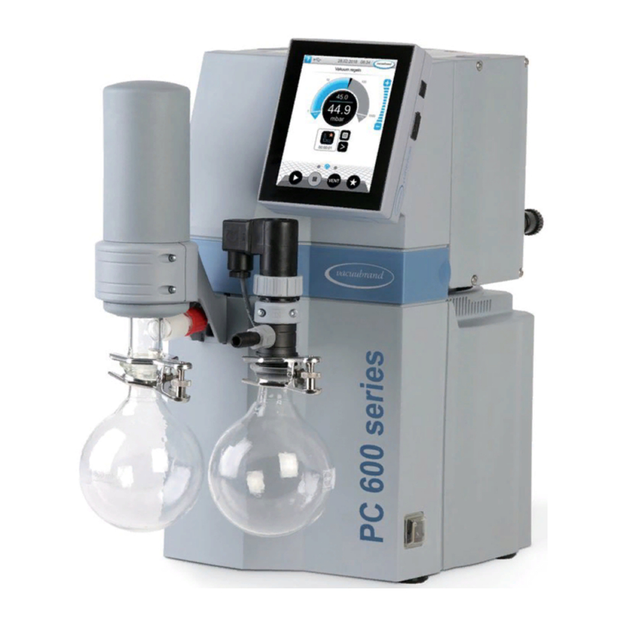
- Page 1 Technology for Vacuum Systems hemistry pumping unit series PC 510 select PC 511 select PC 520 select PC 610 select PC 611 select PC 620 select Instructions for use Original instructions OI no.: 20901101...
- Page 2 +49 9342 808‑5550 ƒ Service +49 9342 808‑5660 Fax: +49 9342 808‑5555 Email: info@vacuubrand.com Web: www.vacuubrand.com Thank you for purchasing this product from VACUUBRAND GMBH + CO KG . You have chosen a modern and techni- cally high quality product. 20901101_EN_PC5xx-6xx_select_Serie_V1.3_260819...
-
Page 3: Table Of Contents
Content TABLE OF CONTENT Introduction User information ....... . . 5 1.2 About this document. - Page 4 Content 4.3.3 Coolant connection at the condenser ... . 38 4.3.4 Venting connection ......39 4.3.5 Gas ballast (GB) .
-
Page 5: Introduction
We reserve the right to make technical changes in the course of ƒ continuous product improvement. Copyright The content of this manual is protected by copyright. Only copies Copyright © for internal use are allowed, e.g., for professional training. © VACUUBRAND GMBH + CO KG 20901101_EN_PC5xx-6xx_select_Serie_V1.3_260819... -
Page 6: About This Document
If your manual is incomplete, you can request a replace- Contact ƒ ment. Alternatively, you can use our download portal: www.vacuubrand.com You are welcome to contact us at any time in writing or by tele- ƒ phone if you would like more information, have questions about our products or wish to share feedback with us. -
Page 7: Display Conventions
Introduction 1.2.2 Display conventions Warning levels DANGER Display conventions Indicates an imminent hazardous situation. Disregarding the situation will result in serious and even fatal injury or death. Take appropriate action to avoid dangerous situa- > > tions! WARNING Indicates a potentially hazardous situation. Disregarding the situation could result in serious, even fatal injury or massive damage to property. -
Page 8: Symbols And Icons
Introduction 1.2.3 Symbols and icons This manual uses symbols and icons. Safety symbols indicate specific risks associated with handling the product. Symbols and icons are designed to help you identify risks more easily. Safety symbols Hazardous substance - General hazards to human health. prohibition sign. -
Page 9: Handling Instructions (Action Steps)
Introduction Additional Flow arrow Flow arrow symbols Inlet – Outlet – exhaust gas vacuum connection 1.2.4 Handling instructions (action steps) Instructions (single step) Display of operating steps > Perform the step described. 5 Result of action Instructions (multiple steps) 1. First step 2. -
Page 10: Term Definitions
Introduction PC ..Pumping unit chemistry with series identification Abbreviations number Polyethylene Polybutylene terephthalate Polypropylene Polyphenylene sulphide PTFE Polytetrafluorethylene PVDF Polyvinylidene fluoride RMA‑N° Return Merchandise Authorization number Wrench size (tool) resp. responsible (supervising) e.g., for example * Labeling on vacuum pump or component ... - Page 11 Both applications electronically controlled. 2 vacuum connections: ` 1x solenoid valve – Process A ` 1x solenoid valve – Process B VACUU·BUS Bus system from VACUUBRAND for com- ® munication between peripheral devices with VACUU·BUS enabled gauges and controllers. ®...
- Page 12 Introduction 20901101_EN_PC5xx-6xx_select_Serie_V1.3_260819...
-
Page 13: Safety Information
Safety information Safety information The complete information of this chapter must be observed by all persons working with the described product herein. The safety instructions are valid for the complete life cycle of the product. 2.1 Usage Only use the product if it is in perfect working condition. 2.1.1 Intended use PC 500/600 select A chemistry pumping unit of the... -
Page 14: Improper Use
Safety information 2.1.2 Improper use Incorrect use or any application which does not correspond to the technical data may result in injury or damage to property. Improper use includes: using the product contrary to its intended use, Improper use ƒ operation at improper environmental and operating conditions, ƒ... -
Page 15: Obligations
Safety information pumping hot, unstable, or explosive media, Foreseeable misuse ƒ pumping substances which may react explosively under impact ƒ and/or elevated temperature without an air supply. The penetration of foreign objects, hot gases and flames IMPORTANT! from the application, must be excluded. 2.2 Obligations 2.2.1 Operator obligations The owner defines the responsibilities and ensures that only... -
Page 16: Target Group Description
Responsible Responsibility Activity Operators Specialist specialist Assignment Matrix Installation Initial use Network integration Operation Error report Remedy Maintenance Repair Repair order Cleaning, simple Empty separator flask Shutdown Decontamination see also website: VACUUBRAND > Support > Instructions for repair Alternatively, arrange for decontamination by a qualified service provider 20901101_EN_PC5xx-6xx_select_Serie_V1.3_260819... -
Page 17: General Safety Information
Safety information 2.4 General safety information Products from VACUUBRAND GMBH + CO KG are subject Quality standards and safety to stringent quality testing with regard to safety and operation. Each product undergoes a comprehensive test program prior to delivery. 2.4.1 Protective clothing... -
Page 18: Laboratory And Working Materials
Safety information 2.4.3 Laboratory and working materials DANGER Hazardous substances could be discharged at the outlet. During aspiration, hazardous, toxic substances at the outlet can get into the ambient air. Observe the national regulations for safe handling of > > hazardous substances. -
Page 19: Eliminate Sources Of Danger
Safety information 2.4.4 Eliminate sources of danger Take mechanical stability into account The high compression ratio of the pump may result in a higher Note mechanical load capacity pressure at the outlet than the mechanical stability of the system allows. >... - Page 20 Safety information Incorrect measurement due to an obstructed vacuum line, e.g., Avoid incorrect condensate in the vacuum line can distort the measurements of measurements the vacuum sensor. > Prevent overpressure > 1060 mbar (795 Torr) inside the suc- tion line. Avoid foreign bodies inside the pump Particles, liquids and dust must not get inside the vacuum pump.
- Page 21 Safety information Risk of burns due to hot surfaces or overheating The surface of the vacuum pump can reach operating tempera- Surface tempera- tures tures > 70 °C, in particular when pumping heated media. > Avoid direct contact with the surface. >...
-
Page 22: Motor Protection
Safety information Keep signs legible Keep labels and information symbols and warning labels always Warning signs and labels in a well readable condition: > Connection labeling > Warning signs and notice labels > Motor data and rating plates 2.5 Motor protection The pump motor has a locked thermal winding protection as over- Overheating protection, deadlock... -
Page 23: Atex Equipment Category
> If necessary vent with inert gas. Information on the ATEX equipment category is also available on our website at: www.vacuubrand.com/.../Information-ATEX 20901101_EN_PC5xx-6xx_select_Serie_V1.3_260819... -
Page 24: Proper Disposal
Safety information 2.7 Proper disposal NOTE Electronic components and batteries must not be disposed of in the domestic waste at the end of their service life. Used electronic devices and batteries contain harmful sub- stances that can cause damage to the environment or human health. -
Page 25: Product Description
Product description Product description Pumping units in the PC 500/600 select series essentially consist of a diaphragm pump with electromagnetic and/or manual inlet valves, a VACUU·SELECT vacuum controller, and a chiller with ® separator. 3.1 PC 511 VARIO select (schematic design) ... - Page 26 Product description Inlet version PC 510/PC 610 Inlet PC 510 select PC 610 select Inlet – vacuum connection (distribution head), with electroni- cally controlled valve 20901101_EN_PC5xx-6xx_select_Serie_V1.3_260819...
-
Page 27: Chemistry Pumping Unit Series
Overview of the PC 500/600 select chemistry pumping units Overview Chemistry pumping units Meaning Chemistry pumping unit Pump head Valve manually Valve electrically a PC 510 select b PC 610 select c PC 511 select d PC 611 select e PC 520 select f PC 620 select... - Page 28 Product description Product-specific abbreviations Separator flask, installed at inlet or outlet Product‑specific abbreviations Vapor condenser, mounted at the outlet PC ..Chemistry pumping unit with type identification number 20901101_EN_PC5xx-6xx_select_Serie_V1.3_260819...
-
Page 29: Condensers And Coolers
Product description 3.3 Condensers and coolers 3.3.1 Separator at the inlet Connection to separator flask Connections at the example PC 510/610 select Meaning Inlet connection vacuum IN 3.3.2 Condenser at the outlet Connection and coolant at vapor condenser Connections at the 11.1 11.2 Meaning... -
Page 30: Examples Of Use
Product description 3.3.3 Examples of use Local vacuum network Example Local vacuum network Meaning Example of use: VACUU·LAN , local area vacuum network with ® three valve modules Vacuum hose* Laboratory furniture PC 611 select vacuum pumping unit Exhaust hose (diverted into an exhaust hood) * pemanent installed PTFE-tubings 20901101_EN_PC5xx-6xx_select_Serie_V1.3_260819... - Page 31 Vacuum drying Example Vacuum drying Meaning Chiller Coolant hoses Outlet hose (diverted into a fume hood) PC 510 select vacuum pumping unit Vacuum hose Example of use: Dryer cabinet Two parallel applications Example Vacuum control of two processes...
-
Page 32: Installation And Connection
Installation and connection Installation and connection 4.1 Transport Products from VACUUBRAND are packed in sturdy, recyclable packaging. The original packaging is accurately matched to your product for safe transport. If possible, please keep the original packaging, e.g., for > >... -
Page 33: Installation
Installation and connection > Lift the unit out of the pack- aging by the recessed grips. > Never use vapor condenser, its holder or glass flask as car- IMPORTANT! rier for placing the pumping unit. They are not designed as carrying aid. - Page 34 Installation and connection Installing the vacuum pump > Place the vacuum pump on a stable, nonvibrating, level, hori- zontal surface. Example 5 cm Sketch Minimum distances in laboratory furniture 5 cm 5 cm > When installing in lab furniture, maintain a minimum distance IMPORTANT! of 5 cm (2 in.) to adjacent objects or surfaces.
-
Page 35: Connection
Installation and connection 4.3 Connection All condensers of the pumping unit series have a vacuum connec- tion and an exhaust gas connection. Perform the connection for your pumping unit as described in the examples below. 4.3.1 Vacuum connection (IN) CAUTION Flexible vacuum hoses can contract during evacuation. - Page 36 Installation and connection Connect vacuum hose Example Vacuum connection at the inlet IN (a) (b) 1. Connect the sealing ring (c), the union nut (b) and the hose nozzle (a) as shown. 2. Push the vacuum hose (d) from the apparatus onto the hose nozzle and secure the vacuum hose, e.g., with a hose clamp.
-
Page 37: Exhaust Gas Connection (Ex)
Installation and connection 4.3.2 Exhaust gas connection (EX) WARNING Risk of bursting due to overpressure inside the outlet line. Inadmissibly high pressure in the exhaust gas line can cause the vacuum pump to burst or damage seals. The exhaust gas line (outlet, gas outlet) must always >... -
Page 38: Coolant Connection At The Condenser
Installation and connection 4.3.3 Coolant connection at the condenser A vapor condenser EK has a connection for coolant liquids. Water Coolant connection or the liquid from a chiller, for example, are suitable coolants. IN = Feed line EX = outlet In a closed, in-house coolant circuit, the pressure should be IMPORTANT! limited to 3 bar (44 psi). -
Page 39: Venting Connection
Installation and connection 4.3.4 Venting connection DANGER Risk of explosion due to venting with air. Depending on the application, venting can cause explo- sive mixtures to form or other hazardous situations to arise. Never vent processes with air which could form an >... - Page 40 Installation and connection Venting with inert gas – connect venting valve Required connection material: Hose for hose nozzle (Ø 4 mm), e.g., silicone hose 4/6 mm. Connection to VENT port 1. Push the hose (l) into the VENT port (k) and fix the tube with the knurled nut 2.
-
Page 41: Gas Ballast (Gb)
Installation and connection 4.3.5 Gas ballast (GB) Use ambient air as gas ballast Example Position of gas ballast valve If ambient air is to be used as gas ballast, nothing needs to be connected at the pumping unit; gas ballast valve (m). ... -
Page 42: Electrical Connection
Installation and connection 4.3.6 Electrical connection Connect pumping unit electrically Example Electrical connection pumping unit 1. Plug the connector (n) on the power cable into the power con- nection of the vacuum pump. 2. Plug power plug (o) into the power outlet. 5 Pumping unit connected electrically. - Page 43 Installation and connection IMPORTANT! > Use the power plug which fits your power supply. > Do not use multi-outlet power strips connected in series as the power connection. > The ON/OFF switch and the mains plug are disconnect- ing devices to separate the pump from the supply voltage. Ensure that the ON/OFF switch and the mains plug are easily accessible at all times to allow the separation of the device from the power supply.
- Page 44 Installation and connection 20901101_EN_PC5xx-6xx_select_Serie_V1.3_260819...
-
Page 45: Initial Use (Operation)
Initial use (operation) Initial use (operation) Apart from the chapters Switch on and Switch off, this manu- al describes the mechanical structure of a pumping unit in the PC 500/600 select series. The operation of the installed vacuum controller and its func- IMPORTANT! tions are described in its own manual VACUU·SELECT. -
Page 46: Operation By Vacuum Controller
Initial use (operation) 5.2 Operation by vacuum controller 5.2.1 Process screen of PC 510 (511) or PC 610 (611) The user interface displays one pressure curve at process screen for vacuum control of up to two applications, one of them elec- tronically controlled. -
Page 47: Process Screen Of Pc 520 Or Pc 620
Initial use (operation) 5.2.2 Process screen of PC 520 or PC 620 The user interface displays two pressure curves at process screen for vacuum control of up to two applications, both electronically controlled. The processes are running mainly independent from each other. - Page 48 Initial use (operation) Assigning process screen Assignment of solenoid valve and process screen Process B *INLET‑V 2 Process A *INLET‑V 1 *VACUU·BUS adress assignment VACUU·BUS Address n° Component VACUU·BUS name addresses split Process A Process B in Process A and In-line solenoid valve INLET‑V 1, 3...
- Page 49 Initial use (operation) To avoid incorrect or simultaneous operation of two processes, the process screens can be switched over. Switch process screen Example > switch from process A to process B > Tap on rear pressure curve. Process B in front. Operation of process B enabled.
-
Page 50: Controller Operation
Initial use (operation) 5.2.3 Controller operation ( see also description of controller) Operating elements Button Vacuum controller Function operating elements active Locked Start ` Start application – only available on the process screen. Stop ` Stop application – always possible. VENT –... - Page 51 Initial use (operation) Start the vacuum controller Example PC 510 Start Stop the vacuum controller Stop Venting Venting 20901101_EN_PC5xx-6xx_select_Serie_V1.3_260819...
-
Page 52: Operation With Gas Ballast
Initial use (operation) 5.2.4 Operation with gas ballast Meaning The provision of gas ballast (= addition of gas) ensures that vapors do not condense inside the vacuum pump but are instead ejected from the pump. This makes it possible to pump larger amounts of condensable vapors and service lives are prolonged. -
Page 53: Shutdown (Switch Off)
Initial use (operation) 5.3 Shutdown (switch off) Take pumping unit out of operation 1. Stop the process and allow the pumping unit to run for Switch‑off pumping unit approx. 30 minutes, with open gas ballast or open inlet (IN). 5 Condensate and media residues will be flushed out of the vacuum pump. -
Page 54: Storage
Initial use (operation) 5.4 Storage Store pumping unit 1. Clean the vacuum pumping unit when it is polluted. 2. Recommendation: Perform a preventive maintenance before storing the pumping unit. Especially if it ran more than 15000 operating hours 3. Close the suction and exhaust connections, e.g., with protec- tion caps. -
Page 55: Troubleshooting
VACUU·BUS plug‑in and cables to the measured connection or cables controller. value defective or not con- nected. Specialist Sensor defective. Replace defective components. 1 -> Phone: +49 9342 808-5660, fax: +49 9342 808-5555, service@vacuubrand.com 20901101_EN_PC5xx-6xx_select_Serie_V1.3_260819... - Page 56 Troubleshooting Error ` Possible cause Personnel Remedy Specialist Venting valve No voltage applied. Check VACUU·BUS plug‑in connection does not op- VACUU·BUS plug‑in and cables to the erate connection or cables controller. defective or not con- nected. Clean venting valve. ...
- Page 57 Troubleshooting Error ` Possible cause Personnel Remedy resp. Spe- Vacuum line too long Use a shorter vac- cialist or cross-section too uum line with a small. larger cross‑section. Operator Condensate inside Allow vacuum pump the vacuum pump. to run for a few min- utes with the suction nozzle open.
- Page 58 Troubleshooting Error ` Possible cause Personnel Remedy Specialist Ball bearing defec- Service the vacuum tive. pump and replace defective parts or Outlet pipe open. send in the device. Glass flask on EK Check exhaust gas missing. line connections. Diaphragm tear or Connect the outlet diaphragm clamping...
-
Page 59: Cleaning And Maintenance
Cleaning and maintenance Cleaning and maintenance WARNING Danger due to electrical voltage. Switch the device off before cleaning or maintenance > > work. Unplug the power plug from the socket. > > Danger due to outdated motor condensers. Condensers can become hot and possibly melt. There can also rarely be darting flames. -
Page 60: Information On Service Work
Cleaning and maintenance 7.1 Information on service work Recommended maintenance intervals Maintenance intervals* If required 15000 h Replace the diaphragms Replace the valves Replace O‑rings Clean or replace molded PTFE-hose Replace pressure relief valve on EK Cleaning Pumping unit * Recommended maintenance interval after hours of operation and under nor- mal operating conditions;... - Page 61 Cleaning and maintenance Tools needed for maintenance Example Tools Tool Size Service kit Service kit MZ 2C NT #20696869 Service kit MD 4C NT #20696870 Diaphragm wrench #20636554 SW66 Flat nose pliers Close hose clamps Flat‑head screwdriver Open hose clamps Gr.
-
Page 62: Cleaning
Cleaning and maintenance 7.2 Cleaning IMPORTANT! This chapter does not contain descriptions for decontamina- tion of the product. This chapter describes simple measures for cleaning and care. > Before cleaning, switch off the Pumping unit. 7.2.1 Housing surface Clean surface Clean dirty surfaces with a clean, slightly damp cloth. -
Page 63: Clean Or Replace Molded Ptfe Hoses
Cleaning and maintenance 7.2.3 Clean or replace molded PTFE hoses Maintenance provides the opportunity to check the components of the Pumping unit, including the hoses. > Clean the inside of very dirty molded hoses, e.g., using a pipe cleaner or similar. >... -
Page 64: Vacuum Pump Maintenance
Cleaning and maintenance 7.3 Vacuum pump maintenance 7.3.1 Maintenance items Items that require maintenance Example Maintenance of the pump heads A = 4‑headed B = 2‑headed Maintenance items Pump heads, power connection side Pump heads, vapor condenser side (EK) IMPORTANT! >... - Page 65 Cleaning and maintenance Exploded drawing of pump head (example) Example Exploded‑drawing pump head PC 610 Valve maintenance Clamping bracket + screw fittings Disc springs Valve terminals Valves O‑rings size 26 x 2 Diaphragm maintenance Head cover + screw fittings Diaphragm clamping disc with square‑head screw Diaphragm Diaphragm support disc...
-
Page 66: Change The Diaphragms And Valves
Cleaning and maintenance 7.3.2 Change the diaphragms and valves Preparation Example Prepare maintenance 1. Switch the Pumping unit off 2. Remove the glass flask from and unplug the power plug. the EK as well as the connect- ed hoses. ... - Page 67 Cleaning and maintenance Disassemble the device and housing sections Example Disassemble housing sections 1. Unscrew the screws from the 2. Remove the housing section counterholder; Torx screw- and set it aside. driver TX20 3. Open the hose clips on the 4.
- Page 68 Cleaning and maintenance Replace the diaphragms Example Diaphragm replacement 1. Press lightly on one of the dia- 2. Lift the diaphragm upwards on phragm clamping discs. either side. 3. Carefully position the dia- 4. Lift the diaphragm, along with phragm wrench on the dia- all the parts, out of the vacuum phragm support disc and...
- Page 69 Cleaning and maintenance Example Diaphragm replacement 5. Pull out the diaphragm clamp- 6. Place the new diaphragm over ing disc and remove the used the square head of the clamp- diaphragm. ing disc. IMPORTANT! > Ensure that the diaphragm is inserted correctly, with the coated, light‑colored side facing upwards.
- Page 70 Cleaning and maintenance Example Diaphragm replacement 9. Hold the spacer discs firmly 10. Initially tighten the assembly and place all the components with the diaphragm wrench carefully on the connecting rod by hand. thread. 11. Then position a torque 12.
- Page 71 Cleaning and maintenance Replace valves Example Valve replacement 1. Take the pump head pair 2. Remove the cap from the gas which you had set aside. ballast. Figure 2–4 optional description, since gas ballast mounted only on one side 3.
- Page 72 Cleaning and maintenance Example Valve replacement 7. Remove the valve terminals Top view: Valve terminals, valves with the disc springs. and pump head pair. NOTICE Valves can adhere to the underside of a valve terminal. 8. Carefully remove the used 9.
- Page 73 Cleaning and maintenance Example Valve replacement 12. Place the new valves on top Cutout view from above: Correct and align them. valve positioning. IN = Inlet (inlet) EX = Exhaust (outlet) 13. Place both valve terminals 14. Place the clamping brackets with the disc springs on the on the valve terminals and pump heads.
- Page 74 Cleaning and maintenance Assemble the device and housing sections Before restarting the pumping unit, all parts of the device and housing which had been removed must be fixed back in place. Example Assemble device and housing parts 1. Carefully press the dia- 2.
- Page 75 Cleaning and maintenance Example Assemble device and housing parts 5. Secure the hose clips on the 6. Put the head cover cowling on hose nozzles, e.g., with flat properly. nose pliers. 7. Screw in the screw connec- 8. Tighten the screw connec- tions of the head cover cowl- tion and close the cover;...
-
Page 76: Replace Pressure Relief Valve On Ek
Cleaning and maintenance 7.3.3 Replace pressure relief valve on EK Pressure relief valve at vapor condenser 20638821 > Pull out the used pressure relief valve and install the new one. Ensure that the PTFE foil under the pressure relief valve lies smoothly on the glass sur- face. -
Page 77: Change Device Fuse
Cleaning and maintenance 7.3.4 Change device fuse At the power connection on the rear side of the pumping unit, there are 2 device fuses, type: 6,3 A/t – 5x20. Change device fuse 1. Unplug the power plug. 2. Carefully pull out the fuse holder. -
Page 78: Appendix
Appendix Appendix 8.1 Technical information Chemistry pumping unit series PC 510 select PC 610 select PC 511 select PC 611 select PC 520 select PC 620 select 8.1.1 Technical data Ambient conditions (US) Technical data Ambient temperature, max. 10–40 °C 50–104°F... - Page 79 Appendix Electrical data Technical data (US) Nominal voltage 230 VAC 100-115 / 120 VAC / Nominal frequency 50-60 Hz 50-60 Hz / 60 Hz Power Surge Category PC 510/511/520 Max. Nominal current 1,8 A 3.4 A Nominal capacity 0,18 kW 0.24 hp PC 610/611/620 Max.
- Page 80 Appendix Weights* and dimensions (l x b x h) (US) PC 510 select 418 mm x 243 mm 16.47 in x 9.57 in x 17.99 in x 457 mm Weight* 17,2 kg 37.9 lb PC 511 select 435 mm x 243 mm 17.13 in x...
-
Page 81: Wetted Materials
Appendix 8.1.2 Wetted materials Wetted materials Component Wetted materials Pump Head cover ETFE carbon fiber reinforced Diaphragm clamping disc ETFE carbon fiber reinforced Diaphragm PTFE Valves FFKM O‑ring Valve terminal ECTFE carbon fiber reinforced Gas ballast tube PTFE carbon fiber reinforced Angle piece (on the valve ter- ETFE/ECTFE minal) -
Page 82: Rating Plate
Appendix 8.1.3 Rating plate Data on rating plate In the event of an error, make a note of the type and serial > > number on the rating plate. When contacting our Service Department, please provide > > the type and serial number from the rating plate. This will allow us to provide you with specific support and advice for your device. -
Page 83: Ordering Information
Appendix 8.2 Ordering information Chemistry pumping unit series Ordering information Order no. for pumping unit PC 510 select 2073315x series PC 511 select 2073325x PC 520 select 2073335x PC 610 select 2073715x PC 611 select 2073725x PC 620 select 2073735x * Order no. - Page 84 Pressure relief valve at vapor condenser 20638821 Gas ballast cap 20639223 Power cable 20612058 20676021 20635997 20635365 20612065 A full list of spare parts available can be found under > > VACUUBRAND > Support > Instructions for repair > Chemistry pumping units. 20901101_EN_PC5xx-6xx_select_Serie_V1.3_260819...
- Page 85 Appendix Sources of supply Purchase original accessories and original spare parts from a International sales offices and subsidiary of VACUUBRAND GMBH + CO KG or your local dis- specialized trade tributor. Information about our complete product range is available >...
-
Page 86: Service
Calibration (DAkkS‑accredited) ƒ With Health and Safety Clearance form: Return, disposal. ƒ > Visit our website for further information: www.vacuubrand.com. Service handling 1. Contact your local distributor or our Service Department. Meet the terms of service 2. Request an RMA no. for your order. -
Page 87: Index
Appendix 8.4 Index Index Abbreviations ....9, 10 Limitation of use ....34 Accessories . - Page 88 Appendix Index Safety information ....13 Safety information for vacuum equipment ... . . 13 Safety precautions ....17 Sales offices .
-
Page 89: Ec Declaration Of Conformity
Chemie‑Pumpstand‑Serie / Chemistry pumping unit series / Groupe de pompage Typ / Type / Type: PC 510 select, PC 511 select, PC 520 select PC 610 select, PC 511 select, PC 620 select Artikelnummer / Order number / Numéro d‘article: 20733154, 20733254, 20733354 20737154, 20737254, 20737354 Seriennummer / Serial number / Numéro de série: Siehe Typenschild / See rating... - Page 90 20901101_EN_PC5xx-6xx_select_Serie_V1.3_260819...
- Page 91 20901101_EN_PC5xx-6xx_select_Serie_V1.3_260819...
- Page 92 Technology for Vacuum Systems Manufacturer: VACUUBRAND GMBH + CO KG Alfred‑Zippe‑Str. 4 97877 Wertheim GERMANY Phone: ƒ Head office +49 9342 808‑0 ƒ Sales +49 9342 808‑5550 ƒ Service +49 9342 808‑5660 Fax: +49 9342 808‑5555 E-Mail: info@vacuubrand.com Web: www.vacuubrand.com...
Need help?
Do you have a question about the PC 510 select and is the answer not in the manual?
Questions and answers