Table of Contents
Advertisement
Quick Links
ER6CD
600 Watt Dimmer
Install Guide
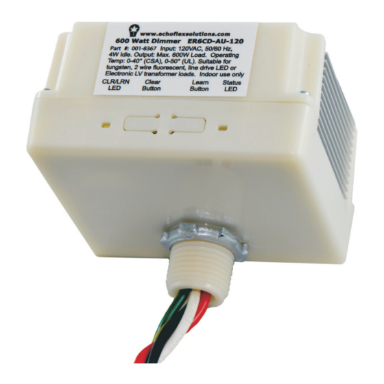
This guide covers all models of the ER6CD lighting controller. The box contents
includes the controller with lock nut and installation guide.
Overview
The ER6CD controller is a 600 Watt dimming controller.
The model ER6CD-AU-120 is phase adaptive and the model ER6CD-AU-277
provides reverse phase dimming control. They both provide dimming control
for line voltage tungsten lamps, 2-wire fluorescent ballasts and line voltage
LED drivers. The ER6CD-AU-120 also controls 120V electronic low-voltage
transformer loads. Neither of these controllers can accommodate magnetic, or
step-down transformer loads.
These controllers have a single channel dimming output and uses wireless
technology to monitor any rooms environment, eliminating much of the wiring
normally required for distributed lighting control. This translates into quick
installations with less disruption to occupants, allowing facilities to accelerate
retrofit schedules and start saving money sooner.
The controller supports several methods of configuration making it easy for
installers and facility operators to manage these settings without extra tools
reducing call-backs and installation expense.
Advertisement
Table of Contents

Related Manuals for echoflex ER6CD


Summary of Contents for echoflex ER6CD
- Page 1 ER6CD 600 Watt Dimmer Install Guide This guide covers all models of the ER6CD lighting controller. The box contents includes the controller with lock nut and installation guide. Overview The ER6CD controller is a 600 Watt dimming controller. The model ER6CD-AU-120 is phase adaptive and the model ER6CD-AU-277 provides reverse phase dimming control.
-
Page 2: Controller Operation
• gateway control implementing scheduled or other events Controller and Wall Switches Echoflex switches can also be used as dimmer switches – press and hold the ON or OFF side of a linked switch to modulate the dimming output up or down. - Page 3 The Echoflex light sensor has two ranges; 0-512 lux (0-50 foot-candles) and 0-1024 lux (0-100 foot-candles). The lighting set point default value is 60% of the sensors Full Scale Range (FSR).
-
Page 4: Electrical Specification
Radio Range Confirmation The “F series” controllers includes patent pending technology that works with all Echoflex sensors equipped with the range confirmation feature to provide visual feedback of a linked sensors signal strength for optimal sensor placement. To evaluate the radio signal strength, the sensor must be also support the test and be linked to the controller. - Page 5 • 120V Electronic low voltage transformer Placement and Radio Range The controller is intended for use with Echoflex wireless sensors and switches. Consideration should be made for locating the controller based on the construction materials and furniture that may disrupt transmissions. Fire doors, elevator shafts, stairwells, storage areas and any large metal objects can create radio shadows and disrupt wireless transmissions.
-
Page 6: Installation
Connect the incoming hot wire (black for 120VAC or brown wire for 277VAC) to the line input feed wire (hot) from the breaker panel. d. Connect the red output wire to the lighting load. Wiring Diagram Orange - Antenna Black 120V ER6CD Brown 277V Green/ Dimmer Neutral Yellow... -
Page 7: Clear Button
Power Up and Test 1. Restore power to the circuit. The dimmer will turn on to full output. 2. Test the circuit by linking a wireless switch (If factory pre-commissioning has been ordered a switch may be linked before delivery). To link a switch: a. -
Page 8: Configuring The Controller
Manually Configure Dimming Mode The dimming mode for the ER6CD-AU-120 Phase Adaptive Dimmer is detected automatically by default. The dimming mode for the ER6CD-AU-277 is reverse phase by default. At the device, you can change the dimming mode manually, entering forward phase, reverse phase, or automatic phase dimming. - Page 9 • Set the motion sensor Auto-OFF timer • Select Daylight Harvesting or Photo Inhibit mode • Set the Light ON/OFF dimming set points for closed loop or open loop Disable/Enable the Auto-ON feature 1. With the light on, tap the occupancy sensors teach button followed by three quick consecutive clicks of a linked wall switch ON.
-
Page 10: Closed Loop
There are two methods of setting the set-point. 1. Closed Loop You can use the light sensor to function as a closed loop sensor. When set as a closed loop sensor, the controller will dim the lights until the light level recorded at the sensor meets the set point value. - Page 11 Linking the First Switch 1. Press the Clear button until the green Learn led blinks ON, approximately 6 seconds. 2. With the controller cleared or in the factory default state, click the wireless switch ON three times, OFF three times and ON three times quickly within 5 seconds. Using this method of linking a switch will only work on the first wireless switch.
- Page 12 disabled by accessing the controller buttons. Press the Learn button and hold, press the Clear button once to disable, twice to enable (this sends the learn telegram). Release the Learn button. The learn LED will blink once when disabling, twice when enabling this telegram.
- Page 13 2. Press ON for 3 seconds. If the dimming output is enabled the light will turn ON, if disabled the light will be OFF 3. Click ON to activate this function, OFF to deactivate. 4. To continue with configuration, press ON for 3 seconds, the light will resume dimming down + up seven times.
- Page 14 • Press ON for 3 seconds. Default setting is 60% of the light sensors full scale range. There are 4 steps from 20% to 80%. The light will blink the step count. (see table below). Click on to increase the set-point, off to decrease the set-point. Taps Max.
- Page 15 This concludes the configuration directions for the controller. Default Settings for Controller Repeater disabled Status disabled Minimum Dimming Output enabled Motion sensor Time-out 15 minutes Switch Time-out no time out Auto-ON Time-out enabled with no linked switch, disabled with linked rocker switch Light-ON-Set point 60% of sensor FSR Light-OFF-Set point...
- Page 16 IC RSS-210 Contains IC: 5713A-STM300U Copyright 2014-2016 Echoflex Solutions, Inc. | Specifications subject to change without notice. Document #8DC-5567 | Revision 2.2| Document 7189M5003 | Rev E Echoflex Solutions, Inc. #1, 38924 Queens Way | Squamish | BC | Canada | V8B 0K8...
Need help?
Do you have a question about the ER6CD and is the answer not in the manual?
Questions and answers