Table of Contents
Advertisement
Quick Links
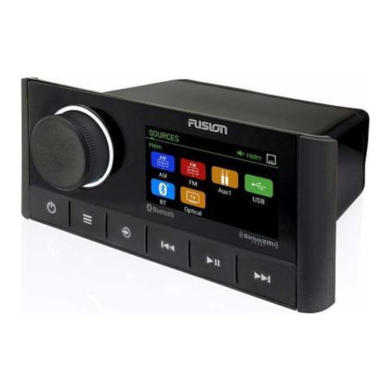
Apollo
MS-RA670 Installation Instructions
™
Important Safety Information
WARNING
Failure to follow these warnings and cautions could result in personal injury, damage to the vessel, or poor
product performance.
See the Important Safety and Product Information guide in the product box for product warnings and other
important information.
This device must be installed according to these instructions.
Disconnect the vessel's power supply before beginning to install this product.
Before applying power to this product, make sure it has been correctly grounded according to these
instructions.
CAUTION
To avoid possible personal injury, always wear safety goggles, ear protection, and a dust mask when drilling,
cutting, or sanding.
NOTICE
When drilling or cutting, always check what is on the opposite side of the surface to avoid damaging the vessel.
Do not use the stereo as a template when drilling the mounting holes because this may damage the glass
display and void the warranty. You must only use the included template to correctly drill the mounting holes.
You must read all installation instructions before beginning the installation. If you experience difficulty during
the installation, contact Fusion
®
Product Support.
What's In the Box
• Mounting gasket
• Four 8-gauge, self-tapping screws
• Two screw covers
• Power and speaker wiring harness
• Auxiliary-in, line-out, and subwoofer-out wiring harnesses
• 2 m (6 ft.) NMEA 2000
®
drop cable
• Dust cover
Tools Needed
• Phillips screwdriver
• Electric drill
• Drill bit (size varies based on surface material and screws used)
• Rotary cutting tool or jigsaw
• Silicone-based marine sealant (optional)
July 2021
GUID-980DCA16-A168-4346-A761-1B2786A5DD83 v5
Advertisement
Table of Contents

Subscribe to Our Youtube Channel
Related Manuals for Garmin Fusion Apollo MS-RA670


Summary of Contents for Garmin Fusion Apollo MS-RA670
- Page 1 Apollo MS-RA670 Installation Instructions ™ Important Safety Information WARNING Failure to follow these warnings and cautions could result in personal injury, damage to the vessel, or poor product performance. See the Important Safety and Product Information guide in the product box for product warnings and other important information.
-
Page 2: Mounting Considerations
Mounting Considerations • You must mount the stereo on a flat surface that provides open airflow around the rear of the stereo for heat ventilation. • If you are installing the stereo in a location that may be exposed to water, you must mount it within 45 degrees of the horizontal plane. -
Page 3: Mounting The Stereo
Mounting the Stereo NOTICE Do not use the stereo as a template when drilling the mounting holes because this may damage the display and void the warranty. You must only use the included template to correctly drill the mounting holes. Be careful when cutting the hole to mount the stereo. -
Page 4: Port Identification
Port Identification Item Description Connects the stereo to the wiring harness for zone 3. Connects the stereo to the wiring harness for auxiliary input 1, and for the line and subwoofer outputs for zones 1 and 2. Connects the stereo to the power and speaker wiring harness. FUSE Contains the 15 A fuse for the device. -
Page 5: Wiring Harness Wire And Connector Identification
Wiring Harness Wire and Connector Identification Bare Wire Color Wire or RCA Connector or RCA Label Notes Function Name Connects to the power source (Power Connection, Ground (-) Black page Connects to the power source (Power Connection, Power (+) Yellow page Connects to the power source (Power Connection,... - Page 6 Bare Wire Color Wire or RCA Connector or RCA Label Notes Function Name ZONE 1 SUB Each subwoofer cable provides a single mono output to a Zone 1 subwoofer out powered subwoofer or subwoofer amplifier. Provides output to an external amplifier, and is associated Zone 2 line out (left) ZONE 2 with the volume control for zone 2.
-
Page 7: Power Connection
Power Connection When connecting the stereo to power, you must connect the yellow, red, and black wires to the power source. The yellow and red wires have different functions, and the method you use to connect them to power depends on how you plan to use the stereo on your vessel. - Page 8 Connecting to Power Without Using an Ignition Switch This method of connection is used most often on larger vessels and on vessels with multiple networked stereos and other marine devices. For these installations, a faster startup time is typically less critical, and it is more effective to use the breaker or a dedicated switch on the electrical panel to turn off the stereo and ensure that no unexpected power drain occurs.
- Page 9 Connecting to Power Through an Ignition Switch This method of connection is used most often on ski boats, wake boats, and similar sport or recreational vessels where power to the engines is toggled often. For these installations, a quick standby and faster startup time is desired so that music can be stopped and begin playing again as quickly as possible after restarting the engines.
-
Page 10: Speaker Zones
Speaker Zones You can group speakers in one area into a speaker zone. This enables you to control the audio level of the zones individually. For example, you could make the audio quieter in the cabin and louder on deck. Up to two pairs of speakers can be connected per channel of each zone, in parallel. - Page 11 Speaker System Wiring Using a Line Out This diagram illustrates a system installation with an external amplifier and subwoofer connected to zone 2 on the stereo using a line out. You can connect an amplifier and subwoofer to any or all of the available zones on the stereo.
-
Page 12: Nmea 2000 System Wiring Diagram
NMEA 2000 System Wiring Diagram Stereo Supported chartplotter, MFD, or compatible Fusion NMEA 2000 remote control NMEA 2000 GPS antenna, speed sensor, or wind instrument. When the stereo is connected to the same NMEA 2000 network as a compatible engine, a GPS antenna, a chartplotter with a built-in GPS antenna, a wind instrument, or a water speed sensor, it can be config... -
Page 13: Fusion Partybus Networking
Configuring an Optional Wired NRX Remote Control NOTICE The stereo is configured by default to work with a NMEA 2000 network, and the NRX POWER option should be enabled only when an optional wired NRX remote control is connected directly to the stereo. Enabling this option when the stereo is connected to a NMEA 2000 network may damage other devices on the NMEA 2000 network. - Page 14 Wired Network Example for Direct Connections No network setting changes are needed when connecting two devices together directly, but for the best results, you should configure one device to be a DHCP server. Fusion PartyBus stereo Fusion PartyBus zone stereo or remote control Wired Network Example with a Switch or Router You must use wired network switches, a wired network router, or both to connect more than two devices.
-
Page 15: Constructing A Network
Constructing a Network You should have a basic understanding of networking when building a network for Fusion PartyBus devices. These instructions guide you through the basics of building and configuring a network, and should apply to most situations. If you need to perform advanced networking tasks, such as assigning static IP addresses to devices on the network or configuring advanced settings on a connected router, you may need to consult a networking professional. - Page 16 The device withstands incidental exposure to water of up to 1 m for up to 30 min, and is protected against powerful jets of water. For more information, go to www.garmin.com/waterrating. The stereo may limit the output power to prevent the amplifier from overheating, and to maintain the audio dynamics.
-
Page 17: Stereo Dimension Drawings
49 mm (1.93 in.) Top Dimensions 157 mm (6.18 in.) 130 mm (5.10 in.) 21 mm (0.83 in.) 10 mm (0.39 in.) Software Updates Go to support.garmin.com to find software updates and information for your device. Apollo MS-RA670 Installation Instructions... - Page 18 物質宣言 有毒有害物质或元素 部件名称 铅 镉 汞 六价铬 多溴联苯 多溴二苯醚 印刷电路板组件 屏幕/背光 金属零件 电缆 电缆组件 连接器 本表格依据 SJ/T11364 的规定编制。 : 代表此种部件的所有均质材料中所含的该种有害物质均低于 (GB/T26572) 规定的限量 產品 : 代表此种部件所用的均质材料中, 至少有一类材料其所含的有害物质高于 (GB/T26572) 规定的限量 *該產品說明書應提供在環保使用期限和特殊標記的部分詳細講解產品的擔保使用條件。 © 2019–2021 Garmin Ltd. or its subsidiaries support.garmin.com...
Need help?
Do you have a question about the Fusion Apollo MS-RA670 and is the answer not in the manual?
Questions and answers