Advertisement
Quick Links
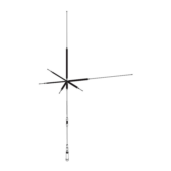
HF ( 3.5, 7, 14, 18, 21, 28MHz )
External view
(Example of 9-band operation)
【Standard specifications】
Frequency Band
3.5 MHz
Antenna Type
Gain
Impedance
VSWR
Max. Input Power
Connector
Length
Weight
COMET Co., LTD.
4-18-2, Tsuji, Minami-ku, Saitama-shi, Saitama-Pref, 336-0026, JAPAN
TEL : +81-48-839-3132
h�ps://www.comet-ant.co.jp
50MHz
144MHz
,
UHV-9
MODEL
Thank you for purchasing our products.
For your safety :
Read this manual carefully for proper handling and opera�on before using.
Keep this manual in a safe place for future reference.
Before assembling
A�er opening the package, check the quan�ty of each part according to the parts list.
【Features】
●
HF band coil is added based on 50MHz band, 144MHz band and 430MHz band.
An antenna that can operate in up to 9 bands.
●
The change in the center frequency fo shift between the 50MHz band and the
144MHz band due to the influence of the HF band coil installa�on is small,
and any combination can be easily operated.
●
With an omnidirec�onal bending mechanism, the element can be removed with
the antenna installed.
●
By using a pipe moun�ng base (RS-215 etc.), it can be easily installed on a fence
such as a balcony.
7 MHz
14 MHz
Loading 1/4λ
0dBi
/ FAX : +81-48-839-3136
9-Bands Antenna
430MHz
&
Main antenna (w/ extended element)
L-3.5 Coil
L-7 Coil
L-14 Coil
L-18 Coil
L-21 Coil
L-28 Coil
7MHz Spare element
14〜28MHz Spare element
Hex. wrench Opposite side 2 mm
Hex. wrench Opposite side 2.5mm
Note1. Spare elements for 3.5 MHz are not included.
Note2. Spare elements are longer than standard.
18 MHz
21 MHz
28 MHz
50Ω (Unbalanced)
Less than 1.5
120W (SSB)
PL-259 (M-Plug)
Approx. 2.1m (Install 3.5MHz coil)
Min. 540 g , Max. 900g
Please note that appearance specifica�ons are subject to
change without no�ce for quality improvement.
Copyright (C) 2020 COMET Co., LTD. All Rights Reserved.
1
Instruc�on Manual
Parts Name
Tip element included
Tip element included
Tip element included
Tip element included
Tip element included
Tip element included
φ1.5×550mm
φ1.5×87mm
50 MHz
144 MHz
1/4 λ
1/2 λ
2.15dBi
2.15dBi
2nd edi�on.
Qty.
1 set
1 set
1 set
1 set
1 set
1 set
1 set
1
4
1
1
430 MHz
5/8λ × 2
5.5dBi
Apr / 2020.
Advertisement

Related Manuals for Comet UHV-9


Summary of Contents for Comet UHV-9
- Page 1 4-18-2, Tsuji, Minami-ku, Saitama-shi, Saitama-Pref, 336-0026, JAPAN TEL : +81-48-839-3132 / FAX : +81-48-839-3136 Apr / 2020. 2nd edi�on. h�ps://www.comet-ant.co.jp Copyright (C) 2020 COMET Co., LTD. All Rights Reserved.
-
Page 2: How To Use
Precautions for handling and operation ● When removing the antenna or bending the element, be careful not to poke your eyes. ● Be careful not to touch the antenna when sending it, as it may generate heat, or you may get burned. ● Regularly check the antenna connector and fixing screws, and �ghten them securely. If it comes ... - Page 3 Notes on installa�on ● When installing, check that the connector of the connec�ng cable is the same type as the connector of the antenna. If they are different types, they may not be connected or may be damaged. ● Securely a�ach the antenna base to the fence. If it is used in a loosened state, it may be blown by the antenna or dropped by the strong wind.
-
Page 4: Notes On Adjustment
The SWR is set to shi�. Basically, the procedure is to cut and adjust the length li�le by li�le while checking the SWR. [Connec�on example] Pipe moun�ng base (RS-215 etc.) Pipe moun�ng base (RS-215 etc.) COMET K series and FS series COMET K series and FS series coaxial cables coaxial cables... - Page 5 ☆ Coil installa�on image and SWR characteris�cs example when using in 3 bands or 4 bands It is possible to operate up to 9 bands by adding each HF band coil See the table on page 4 for the �p to the side bracket.
- Page 6 18, 50, 144, 430MHz 14, 50, 144, 430MHz 18MHz Tip element 14MHz Tip element Element length Approx. 75mm Element length Approx. 80mm Tip element fixing screw Tip element fixing screw 18MHz Coil (L-18) 14MHz Coil (L-14) Element bracket Upper element (φ4×L 45mm) 50MHz choke coil Middle element (φ4×L 405mm) Same as the le�...
- Page 7 7, 50, 144, 430MHz 3.5, 50, 144, 430MHz 3.5MHz Tip element Element length Approx. 503mm 7MHz Tip element Element length Approx. 503mm Tip element fixing screw Tip element fixing screw 7MHz Coil (L-7) 3.5MHz Coil (L-3.5) Element bracket Upper element (φ4×L 45mm) 50MHz choke coil Middle element (φ4×L 405mm) Same as the le�...
- Page 8 ☆ Appearance diagram of coil installa�on and SWR characteris�cs example when using 5 bands ☆ 21, 28, 50 144, 430MHz 18, 28, 50, 144, 430MHz 18MHz Tip element 21MHz Tip element Element length Approx. 75mm Element length Approx. 80mm ...
- Page 9 14, 28, 50, 144, 430MHz 7, 28, 50, 144,430MHz 7MHz Tip element Element length Approx. 503mm 14MHz Tip element Element length Approx. 80mm Tip element fixing screw Tip element fixing screw 7MHz Coil (L-7) 14MHz Coil (L-14) Element bracket Element bracket 28MHz Coil (L-28) 28MHz Coil (L-28)
- Page 10 3.5, 28, 50, 144, 430MHz 18, 21, 50, 144, 430MHz 3.5MHz Tip element Element length Approx. 503mm Tip element fixing screw 18MHz Tip element 3.5MHz Coil (L-3.5) Element length Approx. 75mm Tip element fixing screw 18MHz Coil (L-18) Element bracket Element bracket 21MHz Coil (L-21)
- Page 11 14, 21, 50, 144, 430MHz 7, 21, 50, 144, 430MHz 7MHz Tip element Element length Approx. 503mm 14MHz Tip element Tip element fixing screw Element length Approx. 80mm Tip element fixing screw 7MHz Coil (L-7) 14MHz Coil (L-14) Element bracket Element bracket 21MHz Coil (L-21)
- Page 12 3.5, 21, 50, 144, 430MHz 14, 18, 50, 144, 430MHz 3.5MHz Tip element Element length Approx. 503mm Tip element fixing screw 3.5MHz Coil (L-3.5) 14MHz Tip element Element length Approx. 80mm Tip element fixing screw 14MHz Coil (L-14) Element bracket Element bracket 21MHz Coil (L-21)
- Page 13 7, 18, 50, 144, 430MHz 3.5, 18, 50, 144, 430MHz 3.5MHz Tip element Element length Approx. 503mm 7MHz Tip element Tip element fixing screw Element length Approx. 503mm 3.5MHz Coil (L-3.5) Tip element fixing screw 7MHz Coil (L-7) Element bracket Element bracket 18MHz Coil (L-18)
- Page 14 3.5, 14, 50, 144, 430MHz 7, 14, 50, 144, 430MHz 3.5MHz Tip element Element length Approx. 503mm 7MHz Tip element Element length Approx. 503mm Tip element fixing screw 3.5MHz Coil (L-3.5) Tip element fixing screw 7MHz Coil (L-7) Element bracket Element bracket 14MHz Coil (L-14)
- Page 15 3.5, 7, 50, 144, 430MHz - 5 Bands 3.5MHz Tip element Element length Approx. 503mm Tip element fixing screw 3.5MHz Coil (L-3.5) Element fi�ng 7MHz Coil (L-7) 7MHz Tip element Element length Approx. 503mm Side bracket Upper element (φ4×L 45mm) 50MHz choke coil Freq.(MHz) ...
- Page 16 ☆ External view of coil installa�on and example of SWR characteris�cs when used with 9 bands 3.5, 7, 14, 18, 21, 28, 50, 144, 430MHz - 9 Bands Example of mounting each element [View from above] About moun�ng each element 21MHz Tip element 28MHz Tip element If it is installed near the horizontally installed antenna Element length Element length Approx.
Need help?
Do you have a question about the UHV-9 and is the answer not in the manual?
Questions and answers