Table of Contents
Advertisement
Quick Links
Advertisement
Table of Contents

Related Manuals for FineTek JFR-2 Series

Summary of Contents for FineTek JFR-2 Series
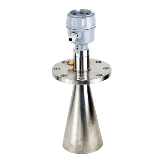
- Page 1 FMCW Radar Level Transmitter Operation Instruction JFR-2 Series FineTek Co., Ltd No.16, Tzuchiang St., Tucheng Industrial Park, New Taipei City 236, Taiwan TEL: 886-2-22696789 FAX: 886-2-22686682 E-mail: info@fine-tek.com http://www.fine-tek.com 08-JFR2XX-B1-EK,11/08/2018...
-
Page 2: Table Of Contents
TABLE OF CONTENTS 1. INSTRUCTION ........................1 2. GUARANTEE ........................2 3. INTRODUCTION ......................... 3 4. SPECIFICATIONS ....................... 4 5. INSTALLATION........................8 6. WRING INFORMATION ...................... 10 7. CALIBRATION ........................11 8. MENU SELECTION ......................13 9. QUICK SETTINGS ......................25 10 TABLE OF COMMUNICATION PARAMETERS .............. -
Page 3: Instruction
1. INSTRUCTION Thank you for your purchasing for FineTek product. This user will introduce the product features, operations, maintenance and troubleshooting to help user get familiar with product, avoid from the possible dangerous use. Before operation, please carefully study the details of product. Extra support can find at www.fine-tek.com or directly contact our representative by telephone and facsimile. -
Page 4: Guarantee
2. GUARANTEE All FineTek products will get one year guarantee in regular operation. Product within guarantee period will get service and no charge for any nominal fee. User finds any defect during delivery process or not be broken by wrong operation that can ask return or replace. In maintenance, user has the obligation to send all complete parts back to FineTek in well carefully package. -
Page 5: Introduction
3. INTRODUCTION FEATURES FMCW Radar level transmitter is a non contact measuring device, which is suitable for high temp., Non contact measurement Ÿ high pressure, and corrosive applications. It is Corrosive and toxic liquid, hydrocarbons, slurries Ÿ easy to install and free of maintenance, especially Not affected by specific gravity, pressure, Ÿ... -
Page 6: Specifications
4. SPECIFICATIONS 1/2"PF 1/2"PF Dimensions (Unit:mm) 1-1/2"PF 2"NPT or 2"PF PTFE PTFE Model JFR-204 JFR-214 General liquid /suitable for acid and General liquid and solid Medium alkaline in liquid Min. Dielectric constant (solid) Min. Dielectric constant (liquid) Measuring range Liquid 30m Solid 20m Liquid 30m Accuracy A3 mm... - Page 7 compressed 1/2" PF air input compressed 1/2" PF air input 1/2" PF 1-1/2" NPT 2"PF Dimensions 2"PF (Unit:mm) f100 f140 Model JFR-224 JFR-234 JFR-244 General liquid and solid Medium Long dlstance Super dlstance Corrosion type acid and Suitable For measurement measurement alkaline liquid Min.
- Page 8 1/2"PF 1/2"PF Dimensions 1-1/2"PF (Unit:mm) 2"NPT or 2"PF PTFE PTFE Model JFR-202 JFR-212 General liquid /suitable for acid and General liquid and solid Medium alkaline in liquid Min. Dielectric constant (solid) Min. Dielectric constant (liquid) Measuring range Liquid 20m Solid 10m Liquid 20m Accuracy A5mm...
- Page 9 compressed 1/2" PF air input compressed 1/2" PF 1/2" PF air input 1-1/2" NPT 2"PF Dimensions 2"PF (Unit:mm) f100 f140 Model JFR-222 JFR-232 JFR-242 General liquid and solid Medium Long dlstance Super dlstance Corrosion type acid and Suitable For measurement measurement alkaline liquid Min.
-
Page 10: Installation
5. Installation 1. JFR-20x can be hidden in the extension tube, the JFR-24x can be hidden in the extension tube, recommendation of the tube diameter D and length L recommendation of the tube diameter D and length L are shown in the table. are shown in the table. - Page 11 10. If drum internal agitator will have a strong vortex and 6. Radar installation should not be too close to the drum foam, drum must increase waveguide, the upper wall, avoid the drum wall attachment material reflection interference. waveguide drill vent holes to ensure the correctness of the measured value.
-
Page 12: Wring Information
6. WRING INFORMATION WIRING INFORMATION WIRING DIAGRAM RS485 wiring JFR-2X4 JFR-2X2 POWER DC24V TR- TR+ Power Supply: V+ RS232/485 Power Supply : V- Converter Analog Output : I+ (4~20mA) RS232 Interface / USB Interface Analog Output : I- (4~20mA) Communication : TR+ (RS485) Communication : TR- (RS485) -
Page 13: Calibration
7. CALIBRATION CALIBRATION 4 wires:With display/adjustment module 2 wires: 1.With display/adjustment module 2. HART Adjustment module is an adjustment tool with 4 buttons to click on. It also has a transparent window to allow display reading. 4 Wires 2 Wires 24V DC. - Page 14 Manual setting 1.1.1 Measurement Low-level adjustment 1.1 Setting 1 Auto setting 1.1.2 Manual setting 1.2.1 High-level adjustment 1.2 Auto setting 1.2.2 Range of blind area 1.3 Scale setting 1.4 Liquid 1.5.1 Material setting 1.5 Powder 1.5.2 Environment setting 1.6 River monitoring 1.6.1 Tank monitoring 1.6.2 Distance 2.1.1.1...
-
Page 15: Menu Selection
8. MENU SELECTION To enter the measuring screen from the main menu, press for 3 seconds. Measuring screen FineTek Main Menu Measurement setting. 16.272 Display setting Echo pattern Option setting CM MM INCH FT % MA Press in the measuring screen to enter the echo pattern. You may also press to return to the measuring screen. - Page 16 1.1.2 Auto Setting The Auto Setting takes the material level value currently measured on site (based on the basis point of the flange surface) as the low point value. Then press in the Low Point Adjustment menu and select Auto Setting 1.1.2. Finally press to save the settings.
- Page 17 1.3 Scope of Blind Area It refers to the distance beyond the detection scope of the product. This function doesn’t require setting. Measurement setting Low point adjustment High point adjustment Scope of blind area Scale setting 1.4 Scale Setting It is to input the tank height. Press in the Measurement Setting menu and select Scale Setting 1.4.
- Page 18 2.2 Display Contrast Adjust the desired display contrast by using , and press to save. Display contrast 3. Echo Pattern From the echo pattern, the user may observe the echo curve of the current signal and make the settings obtain the correct echo value by processing various signals (signal gain, filter setting, signal selection, background noise, signal elimination).
- Page 19 3.3 Signal Gains As shown in the echo pattern, when the interference signal is stronger than the echo signal which may result in misjudgment, the function can be used to select the echo signal to obtain the correct measurement value. Press in the Echo Pattern menu and select Signal Selection 3.3.
- Page 20 3.4.2.2 Cancel It is to perform the reset function. Press in the Reset menu 3.4.2 and select Confirm 3.4.2.2. Finally, press Reset 3.4.2.2 Cancel Confirm 3.5 Signal Elimination It can be used to eliminate all fixed interference noise rather than the echo signal. Press in the Echo Pattern menu 3 and select Signal Elimination 3.5.
- Page 21 3.6 Signal Erasure This function is used to erase the signal before the specified signal. Press in the Echo Pattern menu 3. and select Signal Erasure 3.6. Finally press to save the settings. Echo pattern Signal processing Background noise Signal erasure Signal elimination 3.6.1 Noise Erasure This function is used to erase the signal previous to the desired signal.
- Page 22 3.7.2 Reset It is used to reset the function of Signal Erasure as the default value. Press in the Background Signal menu 3.7 and select Reset 3.7.2. Finally, press to save the settings. Background noise 3.7.2 Eliminate background signal Reset 3.7.2.1 Cancel It is to cancel the reset function.
- Page 23 3.8.2.1 Cancel It is to cancel the reset function. Press in the Reset menu 3.8.2 and select Cancel 3.8.2.1. Finally, press Reset 3.8.2.1 Cancel Confirm 3.8.2.1 Confirm It is to perform the reset function. Press in the Reset menu 3.8.2 and select Confirm 3.7.2.2. Finally, press Reset 3.8.2.2...
- Page 24 4. Options Setting It allows you to calibrate the current, reset and select the unit of the display value and language. Select Options Setting in the main menu, and press to save the settings. Main menu Measurement setting Display setting Echo pattern Options setting Current...
- Page 25 4.2.1 Cancel Press and select Cancel 4.2.1. Finally, press to cancel the reset and go back to the last setting. Reset 4.2.1 Cancel Confirm Press and select Confirm 4.2.1. Finally, press to confirm and all settings will be reset to the factory settings.
- Page 26 5. Connection Setting It is mainly to set the device address and connection speed. Press in the main menu and select Connection Setting 5. Finally, press to save the settings. Main menu Display setting Echo pattern Options setting Connection setting Device address When it is connected with the computer, the FAS address should be the same as the device address to guarantee successful connection, which is 001 by default.
-
Page 27: Quick Settings
9. QUICK SETTINGS To use the product quickly, the user is required to set at least 4 parameters as described below: 1. Low point adjustment (Menu 1.1.1): As shown in the figure below, it is required to input the low point distance from the sealed surface of the flange (the input unit is mm). - Page 28 Display content 1.1.2 Low point adjustment 2.1.1 Distance Manual setting Material height Auto setting FineTek Corporation WWW.FINE-TEK.COM Press and select “Manual Setting 1.2.1”, Press and select Display by “Distance” and then press to enter. or “Material Height”. For example, if you...
-
Page 29: Table Of Communication Parameters
10. TABLE OF COMMUNICATION PARAMETERS Data type Description Privilege Address 4096 STRING Company code Read only Read only 4100 UINT16 Product type 4101 UINT16 Product number Read only Read only 4102 UINT16 Product version FLOAT Distance Read only 4103 4105 UINT16 Distance unit Read only... - Page 30 Communication Data type Description Privilege location Read only 4923 STRING Product part no. 4925 Read only STRING Product serial no. 4927 STRING Production date Read only Read only 4931 STRING Product version 4935 Current lock flag Read only UINT16 Read only 4939 UINT16 Current lock value...
Need help?
Do you have a question about the JFR-2 Series and is the answer not in the manual?
Questions and answers