Table of Contents
Advertisement
Quick Links
Advertisement
Table of Contents

Subscribe to Our Youtube Channel
Related Manuals for Hensel Speed Max


Summary of Contents for Hensel Speed Max
- Page 2 18 / 19...
- Page 3 User manual // Speed Max HENSEL–VISIT GmbH & Co. KG Robert-Bunsen-Str. 3 D-97076 Würzburg-Lengfeld GERMANY Tel./Phone: +49 (0) 931/27881-0 Fax: +49 (0) 931/27881-50 E-Mail: info@hensel.de Internet: http://www.hensel.de HENSEL-VISIT GmbH & Co. KG...
-
Page 4: Introduction
User manual // Speed Max Introduction Thank you for purchasing this Speed Max flash unit. You now own one of the world’s fastest compact flash units. The engineers at Hensel-Visit have put all their long-time experience of manufacturing first class flash equipment... -
Page 5: Table Of Contents
Technical data ............9 Control panel description ........10 Starting up ............11 Safety hints ..........11-12 Acclimatization ..........12 Mounting the Speed Max ......... 12 Protection Glass Dome ........13 Attaching Accessories ........13 Mains Connection ..........14 Fuses ............14-15 Overheat Prevention ........ -
Page 6: General Safety Rules And Information
The quartz (silica glass) flash tube of the Speed Max is specifically matched to the operating conditions HENSEL-VISIT GmbH & Co. KG... - Page 7 The Speed Max must only be used on supply lines (mains) that have an intact protective ground conductor (earth line).
- Page 8 User manual // Speed Max The Speed Max must be protected against humidity, spray water and rain. When operating the unit close to water e.g. a swimming pool, it is very important to prevent the unit from falling into the pool because that...
-
Page 9: Technical Data
User manual // Speed Max Technical Data* Model Speed Max 400 J Rated Flash Power: Guide Number 100 ISO, t 1/60, distance 1m, f 90 2/10 12" reflector, 2 m = (value): (f 32 9/10) Flash Duration (t 0.5) in 1/66.660 s... -
Page 10: Control Panel Description
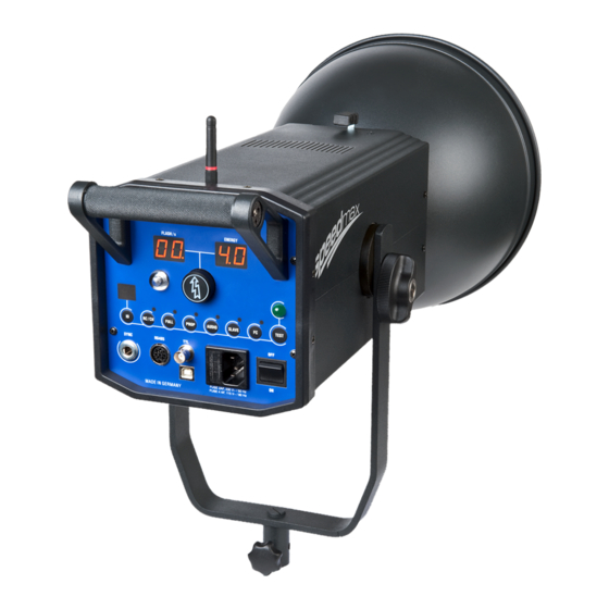
User manual // Speed Max Control Panel Description Release lever for reflector quick-change assembly Display Flash Frequency (FLASH/s, 2 digits, red) Display Flash Power (ENERGY, 2 digits, red) Multifunctional control for Flash Energy and Frequency selection, RC Radio Control Channel Selector, with integrated pushbutton switch for selection of Frequency and Power Priority Mode. -
Page 11: Starting Up
Hensel agency or the Hensel-Visit service department. Installation and Mounting If you intend to use your Speed Max in a ceiling system, pantograph, or other structure, it is required to doubly secure the flash unit in order to prevent it from falling down. -
Page 12: Acclimatization
Mounting the Speed Max Speed Max flash units come equipped with a U-bracket. They can be operated on a light stand or they can be hanging from pantographs or other fixtures. The traditional Hensel U-bracket can be swung through and allows simple locking into the desired position. -
Page 13: Protection Glass Dome
Attaching accessories All Hensel reflectors and Hensel softboxes with the EH series (Ø 10 cm mount) may be attached to the Speed Max flash unit, including umbrellas and Softstars. -
Page 14: Mains Connection
The task for fuse 18 is to protect the modeling lamp circuit. 230V/50Hz The Speed Max requires a 2A-fuse with a blow time rating "fast" (2 AF) for operation on a 230V/50 Hz mains line if a 300W/230V halogen modeling lamp is being used. -
Page 15: Overheat Prevention
Synchronization by slave 5, 12: The Speed Max can also be triggered via its built-in slave SLAVE cell (photo cell) 5, reacting to the light pulse sent by another flash unit. This mode of operation is activated by pushbutton switch 12. -
Page 16: Flash Power Control
Hot Shoe of the camera directly. Using the lateral sliding switch, three different working channels or an 'All' option can be selected. The Speed Max flash units are compatible to the freemask system! More information about the radio control system is available on page 23-24. - Page 17 An adjustment to reduce the flash power setting on the Speed Max does not require any dump action. The selected power is immediately available. Pushing the multi functional control knob 4 will activate either Frequency- or the Flash Power Priority Mode.
- Page 18 User manual // Speed Max flashes at a rate faster than the charging time allows, the trigger attempts in this not-ready-state will be simply ignored. This assures that each flash discharge corresponds to the selected flash power setting. By turning the control knob 4 the desired flash power can 3, 4: be set in 1/10 f-stop increments over a range of 3.0 to...
- Page 19 User manual // Speed Max and ENERGY 3 now list the number of flashes selected last as a four-digit number (0002 to 1000). Examples of readings on displays FLASH/s and ENERGY: Number of Display Display FLASH/s flashes ENERGY Briefly press the multifunctional control 4 to change the number of flashes.
-
Page 20: Flash Readiness
User manual // Speed Max Flash Readiness Flash readiness of the compact flash is signaled by: • the large green READY indicator LED 15 turning on • the modeling light turning on again when operating in the activated Flash Check mode (pushbutton switch 13, FC) •... -
Page 21: Flash Check
RS485 interface. USB Socket The USB socket 20 of the Speed Max can be connected to a USB port of a computer for transferring firmware or for programming purposes. To start the boot loader mode... -
Page 22: Rs485 Interface
Hensel-Visit team for specific information. Error Messages NO FLASH In case a trigger attempt fails the Speed Max will register it as a "NO FLASH" error. The small yellow display 6 will ERROR show the word "NO", the large red display 2 (FLASH/s) MESSAGES "FL", and the large red display 3 (ENERGY) "AS". -
Page 23: Radio Remote Control System Freemask
User manual // Speed Max Radio Remote Control System freemask Utilization The Speed Max flash unit comes equipped with an integrated, freemask-capable radio control receiver compatible to the Hensel Strobe Wizard System. It is able to receive the radio signals from the optional radio control... -
Page 24: Freemask Tips
The slaves of all other flash units, with the exception of the Speed Max, may be left in the activated state. The Speed Max units are able to reach the ready... - Page 25 User manual // Speed Max work area 1, and C2 + F2 for work area 2, and C3 + F3 for work area 3). Camera settings: Use the following settings for the Freemask application if your camera supports them: Frame rate to fastest setting possible ...
-
Page 26: Maintenance And Care
The flash unit must be disconnected from the mains outlet during inspection or cleaning work. Operation on a 230V/50Hz Mains Line The Speed Max flash unit is normally shipped with a 2A 300W/230V fuse with a blow time rating "fast" (2 AF) for operation on Halogen: a 230V/50 Hz mains line. -
Page 27: Replacement Of Modeling Lamp
User manual // Speed Max Should these react to a fault condition the flash unit will switch off. Only an authorized Hensel service station is able to first analyze and then eliminate the fault. If the modeling light fuse has to be replaced make first... -
Page 28: Return To Customer Service
User manual // Speed Max Return to customer service For maximum protection of the flash unit when shipping we recommend that you keep one of the original packaging for each type. Disposal The packaging of the flash unit must be separately disposed of and recycled.
Need help?
Do you have a question about the Speed Max and is the answer not in the manual?
Questions and answers