Table of Contents
Advertisement
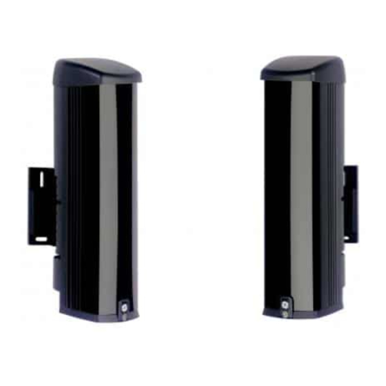
SB Series AIR Beam
Detectors Installation
Manual
EN SB Series AIR Beam Detectors Installation Manual
DE Für eine deutsche Anleitung siehe
www.utcfssecurityproducts.eu/manuals/NT299-ML_RevA_SB_Series.pdf
ES Para manual en Español consultar
www.utcfssecurityproducts.eu/manuals/NT299-ML_RevA_SB_Series.pdf
FR Pour le manuel en Français voir
www.utcfssecurityproducts.eu/manuals/NT299-ML_RevA_SB_Series.pdf
IT Per il manuale in italiano vedere
www.utcfssecurityproducts.eu/manuals/NT299-ML_RevA_SB_Series.pdf
NL Voor de Nederlandse handleiding, gebruik deze link:
www.utcfssecurityproducts.eu/manuals/NT299-ML_RevA_SB_Series.pdf
PT Para Português ver www.utcfssecurityproducts.eu/manuals/NT299-
ML_RevA_SB_Series.pdf
P/N NT299-EN • REV A • ISS 03JUL12
Advertisement
Table of Contents

Related Manuals for Interlogix SB Series


Summary of Contents for Interlogix SB Series
- Page 1 SB Series AIR Beam Detectors Installation Manual EN SB Series AIR Beam Detectors Installation Manual DE Für eine deutsche Anleitung siehe www.utcfssecurityproducts.eu/manuals/NT299-ML_RevA_SB_Series.pdf ES Para manual en Español consultar www.utcfssecurityproducts.eu/manuals/NT299-ML_RevA_SB_Series.pdf FR Pour le manuel en Français voir www.utcfssecurityproducts.eu/manuals/NT299-ML_RevA_SB_Series.pdf IT Per il manuale in italiano vedere www.utcfssecurityproducts.eu/manuals/NT299-ML_RevA_SB_Series.pdf...
- Page 2 Copyright © 2012 UTC Fire & Security. All rights reserved. Trademarks and Interlogix, the SB Series AIR Beam Detectors name and logo are patents trademarks of UTC Fire & Security. Other trade names used in this document may be trademarks or registered trademarks of the manufacturers or vendors of the respective products.
-
Page 3: Table Of Contents
Mono-detection of the bottom beam (optional) 20 Column alignment 22 Response time 23 Replacing the infrared cover 24 Final tests 25 Maintenance 26 Troubleshooting 27 Specifications 29 Default configuration 30 Dimensions 30 Accessories and spare parts 31 SB Series AIR Beam Detectors Installation Manual... - Page 4 SB Series AIR Beam Detectors Installation Manual...
-
Page 5: Introduction
“AND” mode: Simultaneous obstruction of two adjacent cells • “OR” mode: Obstruction of one of the cells Refer to “Installing modules in columns” on page 14 for detailed information on infrared barriers functionality in columns. SB Series AIR Beam Detectors Installation Manual... -
Page 6: General Features
SB450-N, SB4100-N and SB4200-N type detectors are equipped with two cells dual-beam. • 2 operating modes for SB450-N and SB4100-N: “AND” and “OR”. • SB250-N, SB2100-N and SB4200-N have only 1 operating mode: “AND”. SB Series AIR Beam Detectors Installation Manual... -
Page 7: Detector Layout
(4) Infrared cover (11) Cover removal tampers (5) Dual-beam cell (12) Fixing staple for infrared cover (6) Adjustable support Accessories supplied • 8X Ø3.9x13 screws for fixing to column • 1X Installation manual SB Series AIR Beam Detectors Installation Manual... -
Page 8: Installation
Position the holes in the adjustable support over the wall plugs. Note: Rotate the module to be able to reach the screw holes in the adjustable support (see Figure 3 on page 5). SB Series AIR Beam Detectors Installation Manual... -
Page 9: Removing The Infrared Cover
2. Slide the cover upwards until it is stopped by the top plate (item 2). 3. Pull the cover outwards from the grooves in the chassis to remove it (item 3). Figure 4: Removing the infrared cover SB Series AIR Beam Detectors Installation Manual... -
Page 10: Wiring
Selection button Select alignment mode Select cells in alignment mode Alarm LED Intrusion alarm / disqualification (blinking) Level of the signal in alignment Table 1: Terminals Terminal Description “+” Power “−” Power “+” Heating SB Series AIR Beam Detectors Installation Manual... -
Page 11: Dip Switch Settings
“Slave” mode with low beam enabled “Slave” mode with low beam disabled “Master” mode with the mono detection column “Master” mode with double detection column Not used Not used See “Operating modes” on page 11 for more details. SB Series AIR Beam Detectors Installation Manual... -
Page 12: Cable Length
In case of obstruction of the beams (for example, by an object or a person) for more than 60 s, first alarm relay will be triggered, then disqualification relay will be triggered and alarm relay will be reset (see Figure 6 on page 9 for details). SB Series AIR Beam Detectors Installation Manual... -
Page 13: Connecting The Tamper Detection Contact
Remove the PCB at the bottom of the module, connect the two wires and then replace the PCB sliding it in the two grooves until it can go no further, and taking care not to twist the contact strip. SB Series AIR Beam Detectors Installation Manual... -
Page 14: Configuration
When the detectors are placed in the same alignment (see Figure 8 below), allocate different channels to each detector, channel 1 (item 1) to channel 3 (item 3). Figure 8: Multiple channels example (1) Channel 1 (1) Channel 2 (1) Channel 3 SB Series AIR Beam Detectors Installation Manual... -
Page 15: Operating Modes
See Figure 10 on page 12 for modes illustration and DIP switch settings. Caution: The DIP switches settings must be identical on both of 2 associated modules. In OR mode, the response time must be also equal. SB Series AIR Beam Detectors Installation Manual... -
Page 16: Single Module Alignment And Settings
Figure 11: Optical alignment This alignment consists in lining up the optical axes of the modules installed facing each other. This basic alignment adjustment is performed for each module using the integrated sighting system. SB Series AIR Beam Detectors Installation Manual... - Page 17 1. Power cycle the unit (module) - The buzzer beeps 1 time for SB250-N and SB450-N. - The buzzer beeps 2 times for the SB2100-N and SB4100-N. - The buzzer beeps 3 times for the SB4200-N. SB Series AIR Beam Detectors Installation Manual...
- Page 18 Note: In absence of a signal, the buzzer beeps one time per second. [1] The modules SB4200-N, if the continuous beep cannot be reached, try to obtain the quickest beep that is possible. SB Series AIR Beam Detectors Installation Manual...
-
Page 19: Installing Modules In Columns
B (connect the A’s to the A’s and the B’s to the B’s). Recommendation: wire the alarm relays on the module 2 (the second module from the bottom of the column) because this module is recommended to be selected as “Master”. SB Series AIR Beam Detectors Installation Manual... - Page 20 Figure 14: Multiple module wiring (1) to (4) Modules 1 to 4 Inter-module connection SB Series AIR Beam Detectors Installation Manual...
-
Page 21: Setting "Slave" Mode
4 modules inside a column, there should not be gaps or overlaps in the numbering (see Table 8 below). Table 8: Allowed module numbering Position 1 Position 2 Position 3 Position 4 2 modules 3 modules 4 modules SB Series AIR Beam Detectors Installation Manual... -
Page 22: Master" Module Selection
1, 2, 3 or 4. If “Master” is installed in position 1, it is not possible to use the mono-detection of the bottom beam (see “Mono-detection of the bottom beam (optional)” on page 20) for more details. Figure 17: “Master” mode selection SB Series AIR Beam Detectors Installation Manual... -
Page 23: Master" Module Channel Selection
SB4200-N). The detection mode is set on the “Master” module: • Switch 5 of the “Master” module ON to select dual-detection. • Switch 5 of the “Master” module OFF to select simple detection. SB Series AIR Beam Detectors Installation Manual... -
Page 24: Mono-Detection Of The Bottom Beam (Optional)
Mono-detection of the bottom beam (optional) Important Note: Functionality is not available in SB4200-N, SB250-N and SB2100-N modules. The column must be configured in interdetection mode in order to activate the mono-detection of the bottom beam. SB Series AIR Beam Detectors Installation Manual... - Page 25 Figure 20: Bottom beam mono-detection (A) Interdetection mode with mono detection (5) “Master” module settings (B) Interdetection mode without mono detection (6) Dual detection between modules (1) to (4) Modules 1 to 4 SB Series AIR Beam Detectors Installation Manual...
-
Page 26: Column Alignment
2. Press “Select” button of “Master” module (for at least 2 seconds) until the buzzer of “Master” module beeps twice. The red LED blinks once and the buzzer sounds one long beep on “Master” module to indicate the alignment of the bottom cell. SB Series AIR Beam Detectors Installation Manual... -
Page 27: Response Time
This allows the sensitivity of the barrier to be adapted to its environment. A long response time reduces the sensibility of the barrier. (1) “Master” module (2) Potentiometer to set the (3) Response time response time of the intrusion alarm SB Series AIR Beam Detectors Installation Manual... -
Page 28: Replacing The Infrared Cover
2. Slide the cover upwards until it is stopped by the top plate (step 2). 3. Place it flat along the chassis, then slide it downwards and screw in the cover fixing screw (step 3). SB Series AIR Beam Detectors Installation Manual... -
Page 29: Final Tests
Extended interruption of one of two cells for more than 1 min: disqualification alarm. • If the bottom cell is enabled: Movement control in the bottom cell for more than 1.5 sec: intrusion alarm. SB Series AIR Beam Detectors Installation Manual... -
Page 30: Maintenance
Clean the infrared cover of each module at least once a year (or more often, depending on exposure to dirt). • Repeat the final tests (once a year). See “Final tests” on page 25. SB Series AIR Beam Detectors Installation Manual... -
Page 31: Troubleshooting
Single modules only Fault Possible cause Solution Red LED: 1 flash light Module is in “Master” or Turn off the selected mode. “Slave” mode See “Operating modes” on page 11 for more details. SB Series AIR Beam Detectors Installation Manual... - Page 32 14 for more details. Mixing of installed ranges. Verify the compatibility of modules. Put the modules of the same range only. See Table 7 on page 15 for more details. SB Series AIR Beam Detectors Installation Manual...
-
Page 33: Specifications
30 VDC, 500 mA output rating Operating temperature with −25 to +55°C thermostat controlled heating Protection rating IP44 Weight 0,8 kg 0,9 kg 1,1 kg 1,2 kg 1,2 kg Cell direction adjustability Vertically ±10° SB Series AIR Beam Detectors Installation Manual... -
Page 34: Default Configuration
Default configuration For modules default settings see figure 23. Modules are in “AND” mode by default. Figure 23: DIP switch default setting Dimensions All dimensions are given in mm. Figure 24: Detector dimensions SB Series AIR Beam Detectors Installation Manual... -
Page 35: Accessories And Spare Parts
SB27: Cover for column 2m50 • SB32: Cover for column 3m • SB13: Cover for module SB2XX • SB14: Cover for module SB4XX • SB19: Flask bottom and top + tamper card + cable glands SB Series AIR Beam Detectors Installation Manual... - Page 36 SB Series AIR Beam Detectors Installation Manual...
Need help?
Do you have a question about the SB Series and is the answer not in the manual?
Questions and answers