Advertisement
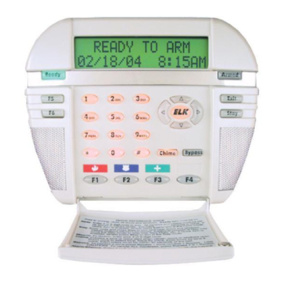
LCD Keypad
APPLICATION
The ELK-M1KP is an addressable LCD Keypad for the M1 Cross
Platform Controls. It features a 32 character back lighted display with
adjustable intensity and extra large character fonts for ease of readabil-
ity. The M1KP includes a plug-in connector on the back for adding an
internal proximity reader (ELK-M1PR) or for interfacing to virtually any
external 26 bit Wiegand compatible proximity reader. Prox cards/fobs
can be used for touchless arming, disarming, door strike control, etc.
FEATURES
! Large, Easy to Read Characters
! Back lighted with Adjustable Intensity
! Removable Hinged Door
! Programmable Function Keys (6)
! Unique Menu Navigation/Direction Keys
! Operates on 4-Wires (M1 Data Bus)
! Adjustable Beep Tone and Volume
! Accepts Plug-in Proximity Card Reader (Optional)
! Input for 1 Supervised Zone
! One Programmable Voltage Output
! Exit, Stay, Chime, and Bypass Keys
SPECIFICATIONS
! Input Connection: 6 Pin Plug-in "Flying Lead" Connector Included
! Prox Connection: 5 Pin Plug-in "Flying Lead" Connector (optional ELK-WO35A required for external prox reader)
! Color: Glacier White
! Operating Voltage: 13.8 VDC
! Current Draw: 40 - 50 mA Idle (low back light level, sounder silent)
160 mA Fully Active (max. back light & sounder active)
! Size: 6.875" W x 5.25" H x 1.375 D
Features and Specifications subject to change without notice.
Data Bus Cable
CAT5 or CAT6 Recommended
To Red (Pos) Wire
To Brown Wire
NOTE: The first batch of M1KP Keypads provided a switched
negative (pull to ground) output. Connect per diagram above.
These units have the letter "E" at the end of the ID number on
the lower back side of the board. EG: PC096E Boards with a
letter "F" or later provide the output as a switched positive.
PO Box 100 • Hildebran, NC 28637 USA • 828-397-4200 Voice • 828-397-4415 Fax
http://www.elkproducts.com • email: info@elkproducts.com
L526 10/05
Hookup Diagram for Keypad
(see M1 Instruction Manual and back of this sheet for multiple Keypad hookups.)
Splice 6 Pin Keypad Wiring Assembly to the Data Bus cable using ELK-900-2 "B" Connectors.
+
Load (50mA max)
-
i.e. Relay, LED
ELK-M1KP
Keypad
Wiring
Keypad 1
BLACK
Assembly
WHITE
1
GREEN
RED
6
BLUE
BROWN
+
To BROWN Wire
Load (50mA max)
-
I.E. LED, Relay
To BLACK (Neg) Wire
Optional programmable Output from Keypad
To BLUE Wire
N.C. N.O.
To BLACK (Neg) Wire
Optional programmable Zone Input from Keypad
ELK-M1KP
See Note about
Data Bus
Termination
The optional Zone Input # or Output # is
determined by the Keypad Address.
KP
Zone Output
KP
Address
#
#
Address
1
193
193
2
194
194
3
195
195
4
196
196
5
197
197
2200
6
198
198
Ohm
7
199
199
EOL
8
200
200
Zone Output
#
#
9
201
201
10
202
202
11
203
203
12
204
204
13
205
205
14
206
206
15
207
207
16
208
208
Advertisement
Table of Contents

Subscribe to Our Youtube Channel
Related Manuals for Elk ELK-M1KP


Summary of Contents for Elk ELK-M1KP
- Page 1 ! Exit, Stay, Chime, and Bypass Keys SPECIFICATIONS ! Input Connection: 6 Pin Plug-in "Flying Lead" Connector Included ! Prox Connection: 5 Pin Plug-in "Flying Lead" Connector (optional ELK-WO35A required for external prox reader) ! Color: Glacier White ! Operating Voltage: 13.8 VDC ! Current Draw: 40 - 50 mA Idle (low back light level, sounder silent) 160 mA Fully Active (max.
- Page 2 Diagram for Daisy Chain Connection of Data Bus Devices Using Two (2) Home Run Cables The ideal way to connect multiple home run cables is with an ELK-M1DBH Data Bus Hub. It accepts CAT5 or CAT6 cable with RJ45 plugs on the ends.
- Page 3 Elk-RP Whenever/And/Then Rules to automatically cause an action or control something. i.e., a fan, pump, light, etc. Viewing a Keypad temperature sensor reading 1. To view a keypad temperature sensor press the ELK key once (enter code if prompted), then press the RIGHT arrow to select the View/Control Automation menu.
- Page 4 Prox cards/fobs are enrolled into a User Code location using the same procedures used to add/change User Code PINs. 1. Press the ELK key, then press the 6 key (or scroll up) to display 6 - Change User Codes. Press the RIGHT arrow key to select this menu.
Need help?
Do you have a question about the ELK-M1KP and is the answer not in the manual?
Questions and answers