Table of Contents
Advertisement
Advertisement
Table of Contents

Subscribe to Our Youtube Channel
Related Manuals for Woods PD35.30


Summary of Contents for Woods PD35.30
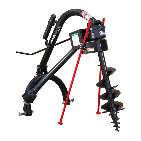
- Page 1 3-POINT MOUNTED General purpose for 12-25 hp tractors with PD25.20 Limited Category 1 hitch Standard-Duty for 20-35 hp tractors with PD35.30 Category 1 or Category 2 hitch Heavy-Duty for 35-95 hp tractors with PD95.50 Category 1 or Category 2 hitch...
-
Page 2: Introduction
TO THE OWNER: Read this manual before operating your Woods equipment. The information presented will prepare you to do a better and safer job. Keep this manual handy for ready reference. Require all operators to read this manual carefully and become acquainted with all adjustment and operating procedures before attempting to operate. -
Page 3: Table Of Contents
TABLE OF CONTENTS INTRODUCTION ..............2 GENERAL INFORMATION. -
Page 4: Specifications
SPECIFICATIONS POST HOLE DIGGER MODEL PD25.20 PD35.30 PD95.50 3-Point Hitch CAT 1, CAT1 CAT 1 or CAT 2 Limited CAT 1 Tractor Horsepower 15 - 25 hp 20 - 35 hp 35 - 95 hp Tractor PTO 540 RPM 540 RPM... -
Page 5: Safety 5
SAFETY RULES ATTENTION! BECOME ALERT! YOUR SAFETY IS INVOLVED! a doctor familiar with this form of injury or gan- Safety is a primary concern in the design and grene, serious injury, or death will result. manufacture of our products. Unfortunately, our CONTACT A PHYSICIAN IMMEDIATELY IF FLUID efforts to provide safe equipment can be wiped ENTERS SKIN OR EYES. -
Page 6: Maintenance
SAFETY RULES ATTENTION! BECOME ALERT! YOUR SAFETY IS INVOLVED! Consult local utilities before digging. Know Use extreme care when working close to fences, location and depth of all underground cables, pipe- ditches, other obstructions, or on hillsides. lines, and other hazards in working area and avoid ... -
Page 7: Transportation
SAFETY RULES ATTENTION! BECOME ALERT! YOUR SAFETY IS INVOLVED! Use a suitable lifting device of sufficient capac- Do not operate auxiliary hydraulics during ity. Use adequate personnel to handle heavy com- transport. ponents. Look down and to the rear and make sure area is clear before traveling in reverse. -
Page 8: Safety & Instructional Decals
Replace decals if they are missing or illegible. Replacement safety decals can be ordered free from your Woods dealer, or in the United States and Canada call 1-800-319-6637. - Page 9 SAFETY & INSTRUCTIONAL DECALS ATTENTION! BECOME ALERT! YOUR SAFETY IS INVOLVED! Replace Immediately If Damaged! 10 - PART NUMBER: 1032572 4 - PART NUMBER: S52020300 CONSULT LOCAL UTILITIES BEFORE DIGGING 9 - PART NUMBER: S52045600 PART NUMBER: 18869 LOCATION: AUGER TUBE 5 - PART NUMBER: 1033176 2 - PART NUMBER: 618529 Safety 9...
-
Page 10: 10 Operation
OPERATION PREPARATION The post hole digger is intended to dig holes in soil free from rocks, tree roots, and other obstructions. It is ARNING designed to be mounted on an agricultural tractor 3- point hitch and powered by an agricultural tractor 540 RPM 6 spline PTO. -
Page 11: Operating Technique
___ Check that equipment is properly and securely 2. Set tractor brakes. Shift tractor into park or neutral attached to tractor. before engaging PTO and digging. Always sit in the operator seat when digging holes. ___ Make sure driveline spring-activated locking pin CAUTION! Always sit in the operator’s seat when slides freely and is seated firmly in tractor PTO spline groove or gearbox PTO spline groove. -
Page 12: Lodged Auger
IMPORTANT 2. With tractor engine off and key removed, Disconnect the PTO driveline from the tractor. ■ Be careful when raising the auger as high as your tractor’s 3-point lift arms can go. This can put 3. Turn the auger backwards with a large pipe wrench the PTO shaft universal joints at an extreme angle until auger is free completely back out of the and cause damage to the PTO shaft! It is best to... -
Page 13: Transport
Raise the implement as high as possible for transport- * Input shield ing. removed for detail STORAGE 1. Drain and change the oil in your gearbox. 2. Check and replace, where necessary, blades, bolts, nuts on the machine. 3. Clean machine and touch up any rust spots that may have appeared. - Page 14 Alternative Suggestions 1. Raise the implement as high as possible. 2. Insert the two parking stand legs (4) into the lug (2) If available, the digger can be hung from an overhead on the front of the gearbox output shield. Secure rafter or beam.
-
Page 15: Owner Service 15
OWNER SERVICE The information in this section is written for operators 3. Grease the PTO shaft daily. who possess basic mechanical skills. For your protec- 4. Check the wear on the cutting blades. Sharpen tion, read and follow all safety information in this man- them routinely with an angle grinder or replace ual. -
Page 16: Replace Cutting Edge
REPLACE CUTTING EDGE CLEAN POST HOLE DIGGER Cutting edges and center points are replaceable. They After Each Use should be sharpened or replaced when worn. Remove large debris such as clumps of dirt, grass, 1. Remove carriage bolt (4), lock washer (5), and hex ●... -
Page 17: Troubleshooting 17
TROUBLESHOOTING PROBLEM POSSIBLE CAUSES & SOLUTION Auger will not dig Shear bolt sheared – install new shear bolt. Teeth dull – sharpen or replace. Ground too dry and hard – order optional down force kit, or wait until it rains. Auger turning too fast and bouncing –... - Page 18 TROUBLESHOOTING PROBLEM POSSIBLE CAUSES & SOLUTION PTO driveline failure Operator raising post hole digger too high above ground when PTO is engaged – causes excessive PTO joint operating angle. PTO is engaged while moving between holes. (Auger swings, which causes excessive PTO joint operating angle.) Improper use of a hard shear bolt –...
-
Page 19: Assembly
ASSEMBLY INSTRUCTIONS ARNING NOTE: On tractors with 3-point arm spacing of 32 inches, place mounting pins on the outside of the yoke assembly. On tractors with 3-point arm spac- Keep hands, feet, hair, and clothing away from ing of 26 inches or less, place mounting pins on the equipment while engine is running. -
Page 20: Install Driveline
3. Secure gearbox to boom using the supplied pin (4) 4. For PD25.20 and PD35.30, loosen the jam nut (6) and cotter pins (3). so that it is flush with the top of the set screw (6, Fig 8.1). Tighten the set screw against the gearbox input shaft. -
Page 21: Attach Auger To Gearbox
IMPORTANT: If the driveline has less than 2 inches of travel left before it bottoms out, follow the Shorten Driveline procedure. Figure 10. Cut Shield (Example) 2. Place the cutoff portion of the shield against the end of the shaft and use it as a guide. Mark and cut the shaft. -
Page 22: Fill Gearbox
Never exceed the recommended auger capac- 1. Level gearbox and remove top fill plug and top ■ ity of the post hole digger. Use of an incorrect sight plug on back side of gearbox. auger or auger extension can cause equipment 2. - Page 23 NOTES Assembly 23 MAN1300 (1/14/2020)
-
Page 24: Post Hole Digger Assembly & Parts List
POST HOLE DIGGER ASSEMBLY 24 Assembly (Rev. 8/3/2020) MAN1300 (1/14/2020) - Page 25 POST HOLE DIGGER ASSEMBLY PARTS LIST PD25.20 PD35.30 PD95.90 DESCRIPTION 612881 612882 613361 BOOM 612762 612761 612761 A-FRAME 602415 602415 613031 GEAR BOX, COMPLETE (INCLUDES 3, 4, 5, 6) 602389 602389 613292 LUG BRACKET S24075100 S24075100 S24075200 INPUT GUARD 613290...
-
Page 26: Appendix
BOLT TORQUE CHART Always tighten hardware to these values unless a different torque value or tightening procedure is listed for a specific application. Fasteners must always be replaced with the same grade as specified in the manual parts list. Always use the proper tool for tightening hardware: SAE for SAE hardware and Metric for metric hardware. Make sure fastener threads are clean and you start thread engagement properly. -
Page 27: Bolt Size Chart & Abbreviations
BOLT SIZE CHART NOTE: Chart shows bolt thread sizes and corresponding head (wrench) sizes for standard SAE and metric bolts. SAE Bolt Thread Sizes 5/16 Metric Bolt Thread Sizes 10MM 12MM 14MM 16MM 18MM ABBREVIATIONS AG ............. Agriculture NC ............National Coarse ATF...... -
Page 28: Repair Parts Warranty
Woods logo are trademarks of Woods Equipment Company. All other trademarks, trade names, or service marks not owned by Woods Equipment Company that appear in this manual are the property of their respective companies or mark holders. Specifications subject to change without notice. -
Page 29: Product Warranty
The limited warranty covers any defects in the material and/or workmanship. Following the proper, recommended installation by an authorized Woods Dealer and normal use of a Woods mounting and backhoe or loader, if a tractor incurs damage resulting from the attachment, Woods will cover the existing tractor warranty in the event the manufacturer voids its tractor warranty because of the attachment. - Page 30 Woods logo are trademarks of Woods Equipment Company. All other trademarks, trade names, or service marks not owned by Woods Equipment Company that appear in this manual are the property of their respec- tive companies or mark holders. Specifications subject to change without notice.
Need help?
Do you have a question about the PD35.30 and is the answer not in the manual?
Questions and answers