Advertisement
Available languages
Available languages
Quick Links
OPTIMUM
®
M A S C H I N E N - G E R M A N Y
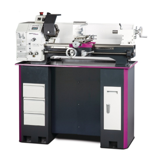
Maschinenunterbau
Produktinformation
Schubfachausbau
Product information
Montage und Installation,
MST1
Machine substructure
3440409
Drawer Removal
Assembly and installation
Maschinenunterbau für Drehmaschinen
Abmessungen - Dimension
Machine base for lathes
Ersatzteile - Spare parts
Advertisement

Related Manuals for OPTIMUM Maschinen MST1


Summary of Contents for OPTIMUM Maschinen MST1
- Page 1 M A S C H I N E N - G E R M A N Y Maschinenunterbau Produktinformation Schubfachausbau Product information Montage und Installation, MST1 Machine substructure 3440409 Drawer Removal Assembly and installation Maschinenunterbau für Drehmaschinen Abmessungen - Dimension...
- Page 2 Um die Maschine mit dem Unterbau zu befestigen, sind zuerst die Schubfächer auszubauen. Schubfachausbau Das obere Schubfach komplett rausziehen. Schubfach Das Schubfach ist jeweils links und rechts mit einer Schubfachsicherung versehen, um ein ungewolltes Herausziehen zu verhindern. Schubfachsicherung links Schubfachsicherung rechts Maschinenunterbau MST1 Seite 2 Originalbetriebsanleitung Version 1.0 vom 2019-09-04...
- Page 3 Den Unterbau am Boden befestigen und erst dann die Drehmaschine auf den vorbereiteten Unterbau mit Spänewanne setzen und miteinander ver- schrauben. Nach dem kompletten Verschrauben können die Schubfächer wieder eingebaut werden. Maschinenunterbau MST1 Version 1.0 vom 2019-09-04 Originalbetriebsanleitung Seite 3...
- Page 4 VORSICHT! Die Angaben der max. Belastung pro Element beziehen sich auf die Summe der statisch plus dynamisch wirkenden Kräfte. Nach dem Absetzen der Maschine darf die Maschine nicht mehr verschoben werden! Maschinenunterbau MST1 Seite 4 Originalbetriebsanleitung Version 1.0 vom 2019-09-04...
- Page 5 Nivellierschraube (Gewindestange) M12x1 x 150mm M16x2 x 150mm Vibrationsdämpfer Ø 47mm Ø 83 mm Hinweis: Der Maschinenunterbau steht auf der Nivelliermutter (2) und nicht auf dem Vibrations- dämpfer (3). SE55 SE85 Maschinenunterbau MST1 Version 1.0 vom 2019-09-04 Originalbetriebsanleitung Seite 5...
-
Page 6: Drawer Removal
Drawer The drawer is provided respectively on the left and right sides with a lock to prevent uninten- tional removal. Drawer lock left Drawer lock right MST1 Machine substructure Page 6 Translation of the original instructions Version 1.0 dated 2019-09-04... - Page 7 Fix the substructure to the floor and only then place the lathe on the prepared substructure with chip tray and screw together. After the complete screwing the drawers can be reinstalled. Machine substructure MST1 Version 1.0 dated 2019-09-04 Translation of the original instructions Page 7...
- Page 8 CAUTION! The max. load per element refers to the sum of static plus dynamic forces. The machine must not be moved after the machine has been lowered! MST1 Machine substructure Page 8 Translation of the original instructions Version 1.0 dated 2019-09-04...
- Page 9 Ø 83 mm Note: The machine base stands on the levelling nut (2) and not on the levelling disc with vibra- tion damper (3). SE55 SE85 Machine substructure MST1 Version 1.0 dated 2019-09-04 Translation of the original instructions Page 9...
- Page 10 OPTIMUM ® M A S C H I N E N - G E R M A N Y Abmessungen - Dimension MST1 Abmessungen - Dimension Originalbetriebsanleitung Version 1.0 2019-09-04...
-
Page 11: Ersatzteile - Spare Parts
OPTIMUM ® M A S C H I N E N - G E R M A N Y Ersatzteile - Spare parts Ersatzteile - Spare parts MST1 Version 1.0 2019-09-04 Originalbetriebsanleitung... - Page 12 OPTIMUM ® M A S C H I N E N - G E R M A N Y MST1 Ersatzteile - Spare parts Originalbetriebsanleitung Version 1.0 2019-09-04...
Need help?
Do you have a question about the MST1 and is the answer not in the manual?
Questions and answers