
Related Manuals for Apex Tool Group Cleco mPro400GCD-P


Summary of Contents for Apex Tool Group Cleco mPro400GCD-P
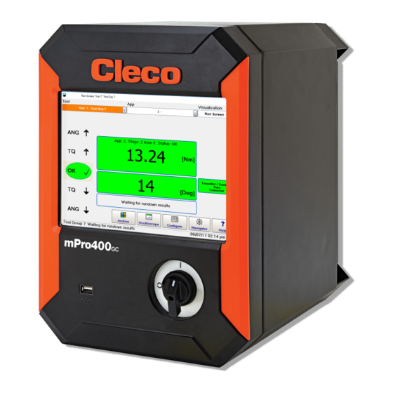
- Page 1 Hardware Description P2300HW-INT 2018-03 mPro400GCD-P Global Controller Primary For additional product information visit our website at www.ClecoTools.com...
- Page 2 Apex Tool Group. Disclaimer Apex Tool Group reserves the right to modify, supplement, or improve this document or the product without prior notice. Trademark Cleco is a registered trademark of Apex Brands, Inc.
-
Page 3: Table Of Contents
Contents Zu dieser Hardware-Beschreibung Sicherheit Produktbeschreibung Technische Daten Steckerbelegung Speicherzugänge Lieferumfang Notes on this Hardware-Description Safety Product Description Technical specifications Pin assignment Storage access Items delivered Acerca de esta descripción del hardware Seguridad Descripción del producto Datos técnicos Asignación de enchufes Acceso a memoria Volumen de suministro System... -
Page 5: Zu Dieser Hardware-Beschreibung
P2300HW 2018-03 Sicherheit Zu dieser Hardware- Beschreibung Grundlegende Die Originalsprache dieser Beschreibung ist Deutsch. Anforderungen Diese Beschreibung richtet sich an alle Personen, die die Steuerung anschließen und installieren. Die verwendete Nehmen Sie die Steuerung erst in Betrieb, nachdem Software ist nicht Gegenstand dieser Beschreibung. ... - Page 6 Das Personal muss durch qualifizierte Mit- werden. arbeiter von Apex Tool Group eingewiesen werden. Die Steuerung wurde von Apex Tool Group voreingestellt. Allgemeine Hinweise, Die Einstellung der Steuerung auf spezielle Anforderungen enthalten Anwendungstipps und nützliche darf nur durch eine qualifizierte Person erfolgen.
- Page 7 Maschinen einführen. Schutzvorrichtungen oder Zubehörteilen ohne schriftli- Nur mit einem einwandfrei funktionierende Schraubsys- che Genehmigung von Apex Tool Group vor. tem arbeiten. Versuchen Sie nicht, die Steuerung oder Komponenten der Steuerung zu öffnen. Weder zur Fehlersuche, noch zu anderen Arbeiten am Gerät.
- Page 8 P2300HW 2018-03 Beim Betrieb Bei der Reparatur Steuerung bei ungewöhnlichen Geräuschen, unge- Reparaturen am Gerät sind unzulässig. wöhnlicher Erhitzung und Vibrationen sofort abschal- ten. Netzstecker ziehen und das Schraubsystem von Bei der Entsorgung qualifiziertem Personal überprüfen und bei Bedarf Bestandteile des Schraubsystems bergen Risiken für reparieren lassen.
-
Page 9: Produktbeschreibung
P2300HW 2018-03 Produktbeschreibung Normative Verweise Produktrelevante EG-Richtlinien sowie eingehaltene Nor- men siehe EG-Konformitätserklärung. Steuerung für den Einsatz bei sicherheitskritischer Ver- schraubungen. Zertifikate Die Schraubersteuerung wird als Steuerungs- und Über- wachungseinheit für ein oder mehrere Werkzeuge an Ausstellende Stelle TÜV SÜD AG einem Arbeitsplatz eingesetzt. -
Page 10: Steckerbelegung
P2300HW 2018-03 Steckerbelegung Alle Anschlüsse sind kurzschlussfest Integrierter Busabschluss. Kein externer Abschluss not- wendig. X5, X6 – Zusatzgeräte Pin Signal 8 pol. M12 Rundsteckverbinder • Alle Ausgänge liefern RS232 konforme Signale. A-codiert • Die Eingänge erlauben Spannungen im Bereich von - N.C. - Page 11 P2300HW 2018-03 X9, X10 – Eingang/Ausgang An diesen Ein- / Ausgangssteckverbindern sind die notwendigen Signalverschaltungen aufgelegt. Die Ver- sorgungen der Signalgruppen sind nicht galvanisch verbunden, es wird getrenntes Auflegen verlangt. • 16 digitale Ein- und Ausgänge, opto-isoliert für 24V-Pegel / 0,5 A •...
- Page 12 P2300HW 2018-03 Signal X9 Signal X10 Bezeichnung Bezeichnung GND2 GND2 GND gemeinsam GND gemeinsam Ausgang O3 Ausgang O7 Ausgang O2 Ausgang O6 Ausgang O1 Ausgang O5 Ausgang O0 (Takten OK) z.B. Ausgang O4 Eingang I3 (Werkzeug Start) z.B. Eingang I7 Eingang I2 Eingang I6 Eingang I1...
-
Page 13: Speicherzugänge
P2300HW 2018-03 Speicherzugänge 4× S909344 M3×5 DIN912 Abb. 6-1: Position der Anschlüsse Pos. Bezeichnung Funktion CF-Karte (Compact Flash) Betriebsystem, Archivdateien und Anwendungen. Im Lieferumfang enthalten. SD-Karte, optional Funktion ist Software-abhängig: Software-Update, Parameter spei- chern/laden, Datenarchivdateien... Nur bei ausgeschalter Versorgungsspannung die CF-Karte ziehen oder stecken. Schwere Systemfehler ... - Page 14 P2300HW 2018-03...
-
Page 15: Notes On This Hardware-Description
P2300HW 2018-03 Safety Notes on this Hardware-Description General requirements The original language of this description is German. This description is intended for all persons who connect and install the controller. The software that is used is not Only operate the controller after you have read this and ... - Page 16 The personnel must be instructed by qualified employees of Apex Tool Group. General notes The controller has been preset by Apex Tool Group. The include application tips and useful informa- adjustment of the controller to special requirements may tion but no hazard warnings.
- Page 17 Do not make any modifications to the controller, protec- During operation tive devices, or accessories without prior written autho- rization from Apex Tool Group. Immediately switch off the controller in case of unusual Do not attempt to open the controller or components of ...
- Page 18 P2300HW 2018-03 At the repair During remote-start operation (multiple tool setup) an inter- Send the complete nutrunner controller for repair to ruption of TSNet bus leads to a delayed stop of the spindle/ your Sales & Service Center. tool. This delay is 2 seconds.Danger due to unexpected start of the motor or due to an expected but missing stop.
-
Page 19: Product Description
P2300HW 2018-03 Product Description Normative References Product-relevant EC directives and the standards complied Each controller is mainly used as a control and monitoring with, see EC Declaration of Conformity. unit for one or more tools at a workstation. Depending on the peripheral devices that are procured, the controller can Certifikates also be installed outside of the work environment. -
Page 20: Pin Assignment
P2300HW 2018-03 Pin assignment X22 – ARCNET system bus All connections are short-circuit proof. The station controller has an integrated bus termination; X5, X6 – Serial port for additional devices therefore, no external termination is necessary. • All outputs provide RS232 conforming signals. Signal 8 pin M12 circular connector •... - Page 21 P2300HW 2018-03 The required signal circuits are connected to these input/output connectors. The signal groups are not gal- vanically connected to the power supply; galvanic isolation is required. • 16 digital inputs/outputs, optically isolated for 24 V level/0.5 A • 8 inputs/8 outputs/2 +24 VDC/2 GND •...
- Page 22 P2300HW 2018-03 Signal X9 Signal X10 Name Name GND2 GND2 Common GND Common GND Output Output Output Output Output Output Output O0 (linking OK), e.g. Output Input I3 (tool start), e.g. Input Input Input Input Input Input Input Output O0-O3 common Output O4-O7 common +24 V2 +24 V2...
-
Page 23: Storage Access
P2300HW 2018-03 Storage access 4× S909344 M3×5 DIN912 Abb. 6-1: Connection positions Pos. Name Function CF card Necessary for the operating system, archive files and applications. Included (Compact Flash) in the delivery SD card, optional Function is software-dependent: software update, save/load parameters, data archive files... - Page 24 P2300HW 2018-03...
-
Page 25: Acerca De Esta Descripción Del Hardware
P2300HW 2018-03 Seguridad Acerca de esta descripción del hardware Requisitos básicos Ponga en funcionamiento el controlador solamente El idioma original de esta descripción es el alemán. después de haber leído y comprendido íntegramente el Esta descripción está dirigida a todas las personas que presente documento. - Page 26 Apex Tool Group. El controlador de apriete ha sido preconfigurado por Este símbolo indica posibles situaciones Apex Tool Group. La configuración del controlador de perjudiciales. ¡ATENCIÓN! apriete para requisitos especiales solamente debe ser rea- Si no se acata esta indicación, pueden pro-...
- Page 27 (p. ej., redundancia de corriente). sorios sin la autorización previa por escrito de Inicie un control por turnos de las máquinas mediante Apex Tool Group. dispositivos de medición. No intente abrir el controlador de apriete o los compo- ...
- Page 28 P2300HW 2018-03 alcohol o medicamentos. Un momento de descuido Separe los distintos componentes del embalaje y elimí- durante el trabajo con la herramienta puede provocar nelos según corresponda a cada tipo. lesiones graves. Entregue la herramienta y el controlador de apriete ...
-
Page 29: Descripción Del Producto
P2300HW 2018-03 Descripción del En caso de funcionamiento fuera de los límites de tensión permitidos, la fuente de alimentación integrada cambia a un modo de protección y producto se desconecta. Este modo de protección puede restablecerse reini- ciando el controlador de apriete. Referencias normativas El controlador de apriete se utiliza como unidad de control Para conocer las directivas CE relevantes, así... -
Page 30: Asignación De Enchufes
P2300HW 2018-03 Asignación de enchufes Todas las conexiones son a prueba de cor- Terminación de bus integrada. No se necesita ninguna tocircuitos conexión externa. X5, X6 – Dispositivos adicionales Pin Señal Conexión de enchufe redondo de 8 pol. • Todas las salidas suministran señales conforme Codificación A RS232. - Page 31 P2300HW 2018-03 X9, X10 – Entrada/salida Estas conexiones de enchufe de entrada/salida tienen asignadas las interconexiones de señal necesarias. Las alimentaciones de los grupos de señal no están conectadas galvánicamente, se requiere su colocación por separado. • 16 entradas y salidas digitales, optoaisladas para un nivel de 24 V/0.5 A •...
- Page 32 P2300HW 2018-03 Señal X9 Señal X10 Designación Designación Apagada Tierra2 Apagada Tierra2 CON. Junto con tierra CON. Junto con tierra Salida Salida Salida Salida Salida Salida Salida S0 (Secuenciado OK) p. ej. Salida Entrada E3 (arranque herramienta) Entrada p. ej. Entrada Entrada Entrada...
-
Page 33: Acceso A Memoria
P2300HW 2018-03 Acceso a memoria 4× S909344 M3×5 DIN912 Fig. 6-1: Posición de las conexiones Pos. Designación Función Tarjeta CF (Compact Sistema operativo, ficheros de archivo y aplicaciones. Flash) Incluida en el volumen del suministro. Tarjeta SD, opcional La función depende del software: actualización del software, guardar/ cargar parámetros, ficheros de archivo de datos... -
Page 34: System
P2349HW-INT 2018-08 System CF-card mPro400GCD-P Main switch Pos. Product Possible connections Serie 30E×N…/50E×N… 1× Serie 18E×E…/48E×E… 1× Serie 17BP…/47BA… 15× Serie 18E×E…/48E×E… + mPro400GC-S 15× Serie 30E×N…/50E×N…+ mPro400GCD-S 15× Access Point ArcNet-Kabel TSNet-Kabel... -
Page 35: Connections
P2349HW-INT 2018-08 Connections Abb. 9-1: Connection positions Designation Designation Ethernet RJ45 10/100 BASE-T Connector #1 I/O Connector Ethernet RJ45 10/100 BASE-T Connector #2 I/O Connector USB V2.0 Port #1 System Bus Connector TSnet USB V2.0 Port #2 System Bus Connector ArcNet Serial RS232-1 Connector #1 Power supply connection Serial RS232-2 Connector #2... -
Page 36: Dimensions
P2349HW-INT 2018-08 Dimensions mPro400GCD-P 327,66 mm (12,900" ) 276,23 mm 266,7 mm (10.875" ) (10,500" ) 381,0 mm (15.000" ) 288,04 mm (11.340") 336,30 mm (13.240" ) - Page 38 Phone: +55 15 3238 3870 Fax: +55 15 3238 3938 EUROPE | MIDDLE EAST | AFRICA Germany Hungary England France Apex Tool Group GmbH Apex Tool Group Apex Tool Group GmbH Apex Tool Group SAS Industriestraße 1 Hungária Kft. C/O Spline Gauges...
Need help?
Do you have a question about the Cleco mPro400GCD-P and is the answer not in the manual?
Questions and answers