
Subscribe to Our Youtube Channel
Related Manuals for Biotek Biolux HOS Series


Summary of Contents for Biotek Biolux HOS Series
- Page 1 Owner's Manual For Your New Biolux HOS Series The Best Choice for Your Family’s Health and Hygiene Healthy Drinking Water | Natural Sanitizer...
-
Page 2: Table Of Contents
HOS - Hydrogen & Ozone Water System Table of Contents Introduction To Our Valued Customers Intended Use Important Safety Warnings and Precautions Product Features Product Specifications Installation Package Contents Unit Overview LCD Display & Control Panel How to Install the Unit Operation &... -
Page 3: Introduction
Introduction To Our Valued Customers Thank you for purchasing Biolux HOS - Hydrogen & Ozone Water System. You have just purchased the finest, most beneficial and advanced health appliance in the world! Your new HOS is designed to provide you with many years of the cleanest, healthiest and most “functional”... -
Page 4: Important Safety Warnings And Precautions
Introduction Important Safety Warnings and Precautions WARNING Please read these pages carefully. They contain very important information to protect you and the valuable warranty on your unit. Please make sure you are familiar with all the safety warning and precautions associated with this unit. - Page 5 Introduction If the power cord develops a break or short, stop using the unit and call customer service to have it replaced. Do not reconnect or splice a defective power cord as it could result in electric shock or become a fire hazard. Do not pull the power cord.
-
Page 6: Product Features
Introduction Product Features • Touch button and color LCD screen for simple operation. • For health improvement, anti-aging and home sanitation. • 99.999% pure Hydrogen and NOx-Free Ozone in outputs. • Zero latency operation, high concentrations right on starting-up. • Built-in gas-liquid separation and off-gas destruction at all time. -
Page 7: Installation
Installation Package Contents Water Outlet Tube (x1) Owner’s Manual ( x1) Input Hose ( PE, white, 1.5 m ) Plumber’s Tape ( x1 ) HOS Main Device (x1) Drain Hose ( PVC, black, 1.5 m ) Connecting Adapter Drain Clamp Mounting Bracket ( x1 ) with Screws ( x2 ) -
Page 8: Unit Overview
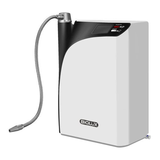
Installation Unit Overview Front View Water Outlet Cap Control Button LCD Display Screen Water Outlet Tube Rear View Hanging Grooves Water Inlet Fitting Drain Fitting SF-100 Faucet Connector Programming Port (Service Use Only) Power Cord Note: The Water Outlet Cap comes with a removable plug that needs to be removed prior to Water Outlet Tube installation. -
Page 9: Lcd Display & Control Panel
Installation LCD Display & Control Panel Drinking Disinfection Waiting Indicator The waiting indicator indicates to wait for certain amount of time before functions can become available. This waiting requirement can be indicated by two modes - light on/blinking under following conditions: Light On: First time start-up - The waiting icon will stay on until system preparation (iEOG water filling process) gets ready •... - Page 10 Installation Internal Cleaning Indicator CLEAN shows that the system is processing internal cleaning. All functions are suspended and little noise is normal during this cleaning period. This function is available both for automatic and manual. In manual mode the water will be discharged from the output.
- Page 11 Installation Power Disconnection Warning • Phase 1 - Within allowed power disconnection limits : Displayed together with accumulated power off times. • Phase 2 - Exceeding allowed power disconnection limits : Displayed together with ERROR (E75) and accumulated power off times (Disconnection reached 72 times or more).
-
Page 12: How To Install The Unit
Installation How to Install the Unit Consult your local Biolux dealer for installation arrangements. The information described below in this section is intended for user’s reference. The most common configurations for home kitchens are discussed here. For additional installation options or questions on your specific installation, please contact your regional Biolux service provider. - Page 13 Installation Typical Scheme of Installation 1. Unit location and setup 4. Connect input water and drain hoses 2. Locate a source for input water 5. Setup and connect the water output 3. Setup input water pre-filter Instruction 1 – Counter-top or Wall-mount Installation Overview Determine if you will place your unit simply on a stable counter or mount it on a wall near and above a sink.
- Page 14 Installation Important: For counter-top installation, two 10 mm holes on the counter will be required for passing the input water and drain hoses through the surface. This is in order to allow the connections from the back of the unit to under sink area for input water and drain.
- Page 15 Installation For under-counter installation, a digital sensor faucet designed exclusively for the unit will be required in order to accomplish the control of output from counter-top. The HOS main device will be located under the sink. While the connections of the input water and drain are accessible directly under the sink, the outlet will be connected to the faucet for output.
- Page 16 Installation Instruction 2 – Input Water Setup Find the ½" to ⅜" Ball Valve T-Adapter (diverter & valve) in the accessory box. Assemble and seal the threaded connection with the plumber’s tape included in the accessory box: Locate the cold water supply under the sink. Shut off water supply. Connect the adapter to the cold water line between the wall and the sink faucet as follows: To your existing faucet Input hose...
- Page 17 Installation Instruction 4 – Input & Drain Connection Remove the joint tube from the unit’s inlet and outlet fittings on the back of the unit. This joint tube is used for shipping purposes only. Find the input hose (white) and drain hose (black) in the accessory box. Insert the input hose into the unit’s fitting (COLD WATER IN).
- Page 18 Installation Instruction 5 – Connect Water Output To locate the water outlet, remove the plastic cap positioned at the top of the unit (rotating water output cap). a. For counter-top installation, find the flexible water outlet tube in the accessory box. Screw the tube anticlockwise into the water outlet until there is no gap.
- Page 19 Installation Connect the faucet and under counter unit and wire the waterproof connectors. ❺ Waterproof connector to faucet ❻ Waterproof connector to under counter unit Connect the faucet and under counter unit and assemble the tubing as shown. ❼ Unit water outlet cap ❽...
-
Page 20: Operation & Use
Operation & Use Unit Start-Up Connection Check Confirm all below points prior to start-up: All inputs, output and drain are correctly installed to their corresponding connections. Ensure that the unit is connected to cold water supply input. The power supply meets the requirements as indicated in the product specifications. Input water pressure is 2.0~7.0 kg/cm (29~100psi). -
Page 21: Directions For Product Use
Operation & Use Directions for Product Use Select a desired water mode: you can choose between Hydrogen Water for Drinking (pressing the upper button) or Ozone Water for Disinfection Use (pressing the lower button) following the below instructions: To Select Hydrogen Water 1. - Page 22 Operation & Use Pre-Filtration Monitoring Program Setting & Life Reset By default, HOS is available with “Pre-Filtration Service Indicator” - the “Life Meter” on the right side of screen that can assist user to monitor the replacement cycle of the filter(s) (or the cartridge(s)). There are total of ten monitoring programs based on treatment capacity for options, from “PF00”...
-
Page 23: Other Functions
Operation & Use Other Functions Drinking pre-flush Drinking pre-flush lasts 5 seconds and is performed during hydrogen water outflow after more than 20 minutes of non-operation, or each time if ozonated water outflow has been used previously within the 20 minutes. “... - Page 24 Operation & Use Service Notification Displays The HOS can display various Service Codes as notifications to users when standard service is required. The information is displayed on the display panel. Please contact your regional Dealer for service arrangements when the code(s) are present. For Remaining Lifecycle of any consumable part that is recorded, the unit will provide service notification once the service or replacement is required.
- Page 25 Operation & Use The coding for each service requirement and the interpretation is listed as follows: Service Code Service Requirement Interpretation Wording translation: S11 Coding Interpretation: Replace Pre-filter Wording translation: S31 Coding Interpretation: Replace Reverse Osmosis(RO) module Wording translation: S32 Coding Interpretation: Replace Deionizer(DI) module Wording translation: S34 Coding Interpretation: Replace Off-Gas Destructor...
- Page 26 Operation & Use Error Notifications Displays For following detectable errors, once detected, the codes will be displayed on the display panel: Error Code Error Interpretation Wording translation: E10 Error Interpretation: iEOG Cell fails. All functions are suspended. Wording translation: E45 Error Interpretation: Preparation (timeout) iEOG water refilling fails during.
- Page 27 Operation & Use Power Disconnection Warnings To maintain the system’s best performance, power must be connected at all times. Unless in necessary situations, such as due to servicing activities or supply outage that may occur occasionally and/or unexpectedly, attempt and care should be made in order to avoid any man-made incidence of power off.
-
Page 28: Recommendations For Using This Unit
Operation & Use Recommendations for Using this Unit Hydrogen & Hydrogen Water Drinking Hydrogen Water helps the selective scavenging of harmful ROS such as hydroxyl and peroxinitrites and preserving the good ROS required. Hydrogen is the newest antioxidant that is capable of increasing the cells and organs' antioxidant, anti- inflammatory and anti-apoptotic abilities. - Page 29 Operation & Use Benefits of Ozone Water Pure ozone and oxygen obtained from pure water electrolysis are used to prepare ozonated water at high concentrations with the process of gas storage, nebulization and efficient pressurization and saturated dissolution. It is safe and reliable in effectively killing bacteria and disinfection. The ozonated water prepared with the pure ozone from pure water electrolysis by electrolytic hydrogen and ozone generator is free from hazardous, or even carcinogenic, toxins such as nitrogen oxides (NOx), nitrates ) and nitrites (NO...
-
Page 30: Service & Maintenance
Service & Maintenance Consumable Parts Consumable Parts Life Cycle Name of Parts Servicing Cycle Depend on filter's capacity or at Pre-filter least 1 year recommended Reverse Osmosis ( RO ) Assembly Deionization ( DI ) Assembly iEOG Cell 2 - 3 years Off-Gas Destructor System Cooling Fan Input Hose... -
Page 31: Troubleshooting Guide
Service & Maintenance Troubleshooting Guide Please check out the following troubleshooting suggestions before calling for repair. Symptom Possible Cause Resolution Is the power cord plugged in Plug the power cord in properly. correctly to an active outlet? Display panel does not light up. Unplug the unit and contact your Electronic failure dealer to arrange service... - Page 32 Service & Maintenance Symptom Possible Cause Resolution Display Code: S31 2% life remaining notification for Replace the notified part. Contact your 2 beeps when pressing any key. Reverse Osmosis module dealer to arrange service ASAP. Display Code: S31 Service due and life ending Replace the notified part.
- Page 33 Biotek Ozone Hong Kong Limited Email: info@biotek-ozone.com.hk Web: www.biotek-ozone.com.hk www.besgroups.com...
Need help?
Do you have a question about the Biolux HOS Series and is the answer not in the manual?
Questions and answers