Table of Contents
Advertisement
Quick Links
Operation & Maintenance Manual
Original Instructions
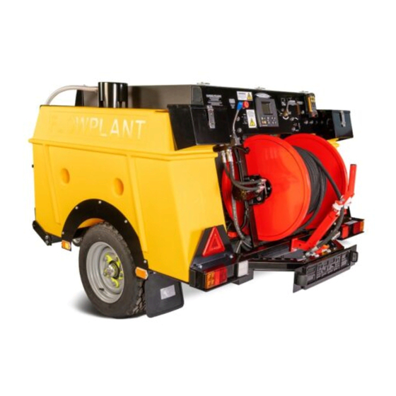
UNIT DTK500 DESILTER TRAILER MANUAL AND
Section 1
Section 2
Section 3
Section 4
Section 5
Section 6
Section 7
Section 8
Section 9
Section 10
Section 11
Section 12
Section 13
061 989
RADIO
(004-424, 004-425)
Contents & Introduction
Scope of Supply
Technical Data
Operation
Routine Maintenance
Fault Finding
Harben P Type Pump
Circuit Diagrams
Diesel Engine
Parts list / Spares / Auxiliary components
Service Documents
Warranty & Certification
Health and Safety Manual 061956
1
Advertisement
Chapters
Table of Contents

Related Manuals for Flowplant DTK500

Summary of Contents for Flowplant DTK500
- Page 1 Operation & Maintenance Manual Original Instructions UNIT DTK500 DESILTER TRAILER MANUAL AND RADIO (004-424, 004-425) Section 1 Contents & Introduction Section 2 Scope of Supply Section 3 Technical Data Section 4 Operation Section 5 Routine Maintenance Section 6 Fault Finding...
- Page 2 Operation & Maintenance Manual for: UNIT: DTK 500 TRAILERR/ 004-424 4012 MANUAL 004-425 4012 RADIOA) ISSUE DATE: 05/21 AMENDMENTS Change Changes Date Signature INITIAL RELEASE 03/21 HAV INFORMATION ADDED TO SECTION 4 05/21 PLUS HOSE SFATETY INFROMATION 061 989...
-
Page 3: Table Of Contents
Contents & Introduction 1.1. Contents CONTENTS & INTRODUCTION ..................3 1.1. C ........................3 ONTENTS 1.2. I ......................6 NTRODUCTION 1.3. S ....................7 COPE OF THIS ANUAL 1.4. T ........................ 7 RAILER 1.5. C ..................8 OMPOSITION OF THIS ANUAL SCOPE OF SUPPLY ...................... - Page 4 4.5. R ) ................22 EMOTE PERATION IF APPLICABLE 4.5.1. S ..................... 22 TARTING THE NGINE 4.6. R ...................... 23 APID HUTDOWN 4.7. A ....................23 UTOMATIC HUTDOWN ® 4.8. H ....................24 ARBEN 4.9. H ................24 OSE REEL WINDING AND UNWINDING 4.10.
- Page 5 10.2. O ..................46 RDERING PARE ARTS 10.3. S ................ 47 ERVICE AND REPAIR PART NUMBERS SERVICE DOCUMENTS .................... 49 11.1. S ....................49 ERVICE HECKLIST 11.2. S ....................51 ERVICE OGBOOK WARRANTY AND CERTIFICATION ................52 12.1. W : ................52 ARRANTY OF NEW PRODUCTS 12.2.
-
Page 6: Introduction
1.2. Introduction Please ensure that you read this Operation & Maintenance Manual in conjunction with the Health & Safety Manual before operation. Within this manual the health and safety risks are highlighted with and you are required to read the relevant section in the Health & Safety Manual. Notices Carefully read the notices of this manual because they give important information concerning safe installation, use and maintenance;... -
Page 7: Scope Of This Manual
• Maintenance of the high-pressure pump. Repairs to the pump crankcase are not considered maintenance operations as these should be undertaken only by FLOWPLANT, their approved agents, or at least competent automotive engineers. 1.4. The Trailer The Trailer is a highly versatile mobile high-pressure water jetting unit, which offers the benefits of proven power pack and pump performance with a comprehensive range of accessories. -
Page 8: Composition Of This Manual
1.5. Composition of this Manual This manual comprises the following further sections: Section 2 Scope of Supply This section defines the scope of supply of the equipment in compliance with the sales order. Section 3 Technical Data This section contains technical information about the unit. Section 4 Operation This section describes the recommended operating procedures for the unit. -
Page 9: Scope Of Supply
Scope of Supply 2.1. Scope of Supply Unit: DTK 500 Desilter Trailer 004424 4012 MANUAL Machine Build Code: 004425 4012 RADIO 2.2. Pump Assembly The General Arrangement drawing No. 004-416 defines the components of the Trailer assembly as follows: The pump is driven by an industrial diesel engine. The engine drives the pump via a reduction gearbox which reduces the pump rpm down to the correct shaft speed. -
Page 10: Detailed Drawings
2.3. Detailed Drawings Detailed drawings and parts lists for the above components are provided as follows: The Pump is detailed in Section 7. Details of other parts and assemblies are included at Section 10. 061 989... -
Page 11: Technical Data
Technical Data 3.1. Technical data 3.1.1. Pump data P Type 8 22 Pump width 405 mm Pump length 385 mm Inlet 28.6 mm dia G1/2” (1/2” BSP) Outlet Shaft dia 30 mm Shaft length 65 mm No. of cylinders Power rating (nominal) 26 kW Piston diameters 22 mm... -
Page 12: Main Components
3.1.2. Main Components 004-416 / 004-422 Engine Kubota D1803-CRT-E5B-UEU 020143 – Harben Reduction 2.00:1 Gearbox _________________________________________________________________________ 3.1.3. Ancillaries Water tank 500 Litres Nominal Capacity Supply filter N05105 Hypro Line Strainer / 80 Micro Mesh Monitoring & Control Murphys MPC-20 Pressure Control and Safety Pressure Transmitter 0-300 bar ________________________________________________________________________ 3.1.4. -
Page 13: Technical Description
3.2. Technical Description 3.2.1. Primary Components The primary components of the trailer are as follows: • A prime mover in the form of an industrial diesel engine which drives a high-pressure pump. • The pump is capable of producing high-pressure water Note: See above or section 7 for performance options. - Page 14 3287 1690 FILLING POINT (BALLCOCK HOUSING) HYDRAULIC HOSE REEL (DELIVERY) WATER SADDLE TANKS (PLASTIC) P-TYPE PUMP HOSE REEL (INLET) COUPLING INDUSTRIAL ENGINE DRAIN VALVE WATER TANKS HYDRAULIC MOTOR HOSE FEED GUIDE JOCKEY WHEEL...
-
Page 15: Operation
Operation 4.1. Operating Conditions Operators of water jetting equipment should be fully conversant with the 'WJA Code of Practice for the use of high-pressure water jetting equipment’, hereafter referred to as 'The Code of Practice'. A copy of The Code of Practice is available upon request. Please ensure that you read this Operation &... -
Page 16: Starting The Engine And Setting The Operating Pressure
4.4. Starting the Engine and Setting the Operating Pressure With two people, one at the pump set and one in charge of the nozzle or gun. Tank water level Ensure you have an adequate water supply and that the water tank is filled to the ball valve shut off level. -
Page 17: Checking The Operating Pressure With A Nozzle Fitted
4.4.2. Checking the Operating Pressure with a Nozzle Fitted 1. Fit the correctly sized nozzle to the high-pressure hose. 2. Ensure the nozzle is in a safe position placed inside the pipe to be cleaned and preferably within sight of the operator at the control panel. 3. -
Page 18: Dpf Regeneration
4.4.3. DPF Regeneration Periodically the Engine will need to perform a DOC Regeneration Cycle. Ensure the Unit is parked up with the handbrake applied, in a non-combustible environment. Ensure the Unit is full of water, and on DUMP. As this process is noisy and can take time, it is recommended that it is not undertaken at night. - Page 19 5) Start machine on idle with the water returning to tank. 6) Enter the Engineers pages on the Control Panel by selecting. Input the Password to gain access. 1111. 7) Select the “Engine Settings” option within the menu by scrolling and pressing enter. 8) In the next screen select “Tier 4”...
- Page 20 10) The Engine RPM will then increase automatically to conduct the full Regeneration. The symbol will now be solid. 11) The Engine will now run until completion of the Regeneration Cycle. This can take some time. Throughout the Cycle, the following symbols will appear simultaneously. 12) Once the Regeneration Cycle has finished, the Engine will return to idle.
- Page 21 IMPORTANT NOTES: Running unit on idle for prolonged periods will result in build-up of soot and require engine to complete a passive or forced regeneration. Running the unit on prolonged periods at full load and full speed will clear the DPF and reduce the requirement for passive or forced regeneration.
-
Page 22: Remote Operation (If Applicable)
4.5. Remote Operation (if applicable) 4.5.1. Starting the Engine 1. Switch on the Panel using the I/0 Rocker switch. 2. Enter the PIN using the & Arrows and buttons on the controller. 3. Press the remote function on the controller and press to enable remote. -
Page 23: Rapid Shutdown
Turning the unit ON • Pull out the red button at the base of the RCU • Press both buttons 5 & 6 together and hold for at least 3 seconds until a beep is heard. Once connected, the screen should display as per Fig. -
Page 24: Harben ® Jump Jet
® 4.8. Harben Jump Jet The Harben Jump Jet system is a unique and exceptionally effective addition to the Harben high pressure pump which increases the effective duct cleaning distance up to and often beyond 300m. When required the operator can switch on the Jump Jet to create a cyclic vibration in the jetting hose. - Page 25 If broken duct is suspected – dig up might be only option to retrieve hose. Coil up hose and leave in box. NOTE: More tips on safe handling of hoses can be found on the Flowplant website. See link below. https://www.flowplant.com/wp-content/uploads/2021/05/Hose- safety.pdf...
-
Page 26: Frost Precautions
4.10. Frost Precautions During cold periods there is a risk of freezing overnight or when travelling on the road. Damage caused by freezing is expensive to repair and IS NOT COVERED UNDER WARRANTY. Take the following precautions to avoid frost damage: 4.10.1. - Page 27 Open the yellow valve from the tank marked ANTIFREEZE. This tank must be full of an antifreeze mixture with strength of no less than a 50/50 mix. Remove the gun or any jetting nozzle from end of the hose and unreel 3m of hose.
-
Page 28: To De-Antifreeze The Machine
4.10.2. To De-Antifreeze the machine: 1. Shut off the 2-way antifreeze valve. 2. Place the 3-way valve into the RUN Position. See picture below. 3. Re-fill the water storage tank. 4. Put jump jet valve into the ‘off’ position, see below. 5. -
Page 29: To Antifreeze Without An Antifreeze Tank
4.10.3. To antifreeze without an antifreeze tank: 1. Prepare 50/50 antifreeze solution. 2. Remove nozzle or gun attachments from the delivery hose. 3. Lower the water level in the tanks using the drain valve immediately to right of the o/s wheel. -
Page 30: Routine Maintenance
Check air filter cleanliness (Ref section 10) • Check fuel filter for contamination (Ref section 10) • Three monthly / 50 hours First service contact Flowplant • Replace Pump Oil (only required for first service only) • Six Monthly / 100 hours Inspect tanks and fittings for leaks •... -
Page 31: Daily Maintenance
5.2. Daily Maintenance The following must be completed daily with the trailer switched OFF. 1. Check condition of inlet water filter & element. Clean or replace. (Flowplant part no. N05105) Unscrew the bowl to remove the mesh (Flowplant part no. N06021). Take precautions so as not to lose the sealing ring (Flowplant part no. -
Page 32: P-Pump Lubricating Oil
5.3. P-Pump Lubricating Oil Manufacturer Type Oil Capacity (litres) Number of Cylinders ESSO Nuto H150 GULF LP 150 3-cyl 4-cyl 6-cyl 8-cyl MOBIL DTE Extra Heavy 5.75 Kiron 150 TEXACO Rando HD 150 Energol HLP 150 AGIP OSO 105 SHELL Tellus/Morlina 150 CENTURY OIL PWLM... -
Page 33: Safety Relief Valve
5.4. Safety Relief Valve The DTK500 trailer is fitted with a safety relief valve which will lift at 15% working pressure. This will protect the machine and will lift before the rated pressure of any component on the trailer. The trailer working pressure is 275bar (4000psi) and the safety relief valve will lift at 316bar (4600psi). -
Page 34: Fault Finding
Fault Finding Most of the problems experienced during jetting operations are likely to be caused by the pump or the associated hoses. These types of problems are covered in the pump fault finding chart, which is repeated at 6.3 overleaf for convenience. Also covered at 6.3 overleaf is a diagnosis of selector valve problems. -
Page 35: Equipment Fault Finding
6.2. Equipment Fault Finding Problem Possible Cause Recommended Action Low system pressure 1 Worn or incorrect size of Replace the old jetting cutting nozzle. Nozzle with a new one. 2 Engine speed slow. Adjust to correct speed. 3 Leaks from hose. Pipes and Check the connections for connections. -
Page 36: P-Pump Fault Finding
6.3. P-Pump Fault Finding Problem Possible Cause Recommended Action 1 Check all delivery valves – 1 Mixing of Oil and Water 1 Worn or damaged delivery in crankcase valves. replace as necessary. 2 Check all diaphragms – 2 Loss of pressure 2 Damaged filter element allowing debris to jam delivery replace as necessary. - Page 37 DISTINGUISHING FEATURE OF FAILURE ON DIAPHRAGM Impression of the baffle on diaphragm Reason: Delivery valves worn or blocked DISTINGUISHING FEATURE OF FAILURE ON DIAPHRAGM 4 small impressions cause more damage on the inside, than on the outside. Reason: Water filter blocked, or inlet valves blocked. DISTINGUISHING FEATURE OF FAILURE ON DIAPHRAGM Shear through wall of diaphragm Reason: Pump operated whilst frozen or wear and tear after several thousand hours...
-
Page 38: Selector Fault Finding (See Section 8)
6.4. Selector Fault Finding (see section 8) Selector problem Cause Action Loss of pressure and flow is Water leaking through the Replace the seats and the down. worn seat back to tank. plug if also damaged. If water leaks along spindle O-ring and back up ring Replace O-ring and back up and past lever. -
Page 39: Pump
Pump P-Type Refer to the P Type Pump Service Manual, part no. 061-352, included with the unit. 061 989... -
Page 40: Circuit Diagrams
Circuit Diagrams The following circuit diagrams are included in this section: Hydraulic circuit This provides details of the unit’s hydraulic circuit, the function of which is to power a hydraulic motor driven hose reel, winding high-pressure hose in or out whilst carrying out drain cleaning or other high-pressure water jetting applications. -
Page 41: Hydraulic Circuit
8.1. Hydraulic Circuit 061 989... -
Page 42: Water Circuit
8.2. Water Circuit 061 989... -
Page 43: Electrical Circuit
8.3. Electrical circuit 061 989... - Page 44 This page is left blank intentionally 061 989...
-
Page 47: Diesel Engine
Diesel Engine Copies of the Diesel Engine Manufacturer’s Operators Handbook are supplied with this equipment. 061 989... -
Page 48: Parts Lists / Spares
To identify components for the pump or engine etc, refer to the relevant parts in this manual. 10.2. Ordering Spare Parts Order spare parts from: Flowplant Group Ltd Gemini House, Brunel Road, Churchfields Industrial Estate Salisbury, Wiltshire, UK, SP2 7PU Tel. +44 (0)1722 325424 – Fax. +44 (0)1722 411329 sales@flowplant.com... -
Page 49: Service And Repair Part Numbers
10.3. Service and repair part numbers ITEM FLOWPLANT PART NO DESCRIPTION QTY CODE 051-1077 Engine Oil Filter 051-1078 Engine Fuel Filter 051-1079 Engine Air Filter Inner 051-1080 Engine Water Temp Sensor 051-1081 Alternator Fan Belt 051-1090 Engine Air Filter Main... - Page 50 FLOWPLANT PART ITEM DESCRIPTION QTY CODE 020-143 Gearbox 023-011 Angle Swivel Joint 90 deg 024-184 Diverter Valve Seal Kit 035-255 Diverter Valve 035-445 Jump Valve 051-1082 Engine Alternator 051-1083 Engine Starter Motor 067-779 Safety Relief Valve 069-581 Diverter Valve Installation...
-
Page 51: Service Documents
Service Documents 11.1. Service Checklist 061 989... - Page 52 SERVICE CHECK LIST Serial Number - Unit Number - Sht 1 of 2 Date - Engineer - Hours Run - ESR - In: - Initial Service 1Y:- 1 Yearly Service 2Y:- 2 Yearly Service O:- Other Services Engine Hydraulics* Water/Anti-freeze tanks Mins 1Y 2Y Mins...
-
Page 53: Service Logbook
11.2. Service Logbook 061 989... -
Page 54: Warranty And Certification
Provided always that: • They are returned to Flowplant for inspection (carriage paid), along with a copy of the original part(s) sale invoice (where necessary); and • All terms agreed by Flowplant for payment of such goods have been complied with;... -
Page 55: Limitations Of Warranty
• Repaired or altered in any way so as, in the judgement of Flowplant, to adversely affect its performance and reliability 12.3. Limitations of warranty: The new product and spare parts warranty is limited to defects in material or workmanship of the product. - Page 56 Page left intentionally blank 061 989...
-
Page 57: Declaration Of Conformity
12.4. Declaration of Conformity 061 989... - Page 58 Page left intentionally blank 061 989...
-
Page 59: Certificate Of Conformity
12.5. Certificate of Conformity 061 989... - Page 60 Page left intentionally blank 061 989...
-
Page 61: Health And Safety Manual - 061956
Health and Safety Manual – 061956 061 989... - Page 62 This page is left blank intentionally 061 989...
- Page 63 HEALTH AND SAFETY MANUAL – Issue 1 Read before operating equipment Flowplant high pressure jetters and systems have been designed to the highest standards so that they will work safely and reliably for many years. It is important that you take time to read the safety information provided here so that you understand how to make the most of the equipment and how to use it safely.
- Page 64 Change Changes Date Signatu NEW ADDITION 09/19 GENERAL EDIT 01/20...
- Page 65 Contents General Safety Information ......................4 General use of High Pressure Jetters ..................5 Hazards Associated with the misuse of High-Pressure equipment ..........6 Personal Protective Equipment ....................9 Pressure Safety Devices ......................10 High Pressure Hoses ......................... 11 Pump Bleed Screws ........................12 Exhaust Gases &...
-
Page 66: General Safety Information
General Safety Information Safety procedures throughout this manual must be adhered to. In the case of conflicting or ambiguous instructions contact your Site Manager or Safety Manager before commencing work. Any person operating, working with, or passing near the jetter must wear the appropriate Personal Protective Equipment (PPE). -
Page 67: General Use Of High Pressure Jetters
General use of High Pressure Jetters All persons using high pressure jetting equipment must be fully conversant with relevant operating instructions, safety notes and codes of practice. Operators must be competent in all aspects of jetter use. Erect suitable cordons at least 10m from the jetting operation to restrict all unauthorised access. -
Page 68: Hazards Associated With The Misuse Of High-Pressure Equipment
Hazards Associated with the misuse of High- Pressure equipment Never use a jetter that isn’t regularly serviced according to the manufacturer’s recommendations. When a jetter is used to clean drains & sewers that are contaminated with a hazardous substance it is possible these may be entrained in the resulting aerosol and inhaled by operators. - Page 69 Never attempt to clean drains or pipes in one pass because this could lead to debris build up behind the jet nozzle causing a pressure build up in the drainage system. Be aware that a pressure build-up in the drain or pipe could cause the jet nozzle to be unexpectedly ejected back towards the operator.
- Page 70 Never work from a ladder as the reaction force of the jetting gun could cause the ladder to fall backwards from the working area causing possible injury. Never work from scaffolding unless it is designed, erected and managed by competent persons and it is adequately secured to prevent it being pushed over by jetting gun reaction forces.
-
Page 71: Personal Protective Equipment
Personal Protective Equipment Before operating jetting equipment all persons must carry out a risk assessment to determine the type and level of PPE required by each member of the jetting team. This could include: Ear protection – noise levels can be high ... -
Page 72: Pressure Safety Devices
Pressure Safety Devices Pressure relief valves should be checked for functionality and certified by the manufacturer or their authorised representative at least every 6 months. Pressure discs (burst discs) should be replaced at least every 6 months to ensure continued safe operation and only manufacturer’s original replacements should be used. -
Page 73: High Pressure Hoses
High Pressure Hoses Hose assemblies require careful handling to provide long service life and to guard against potentially dangerous failure. Serious injury and death can result from the failure of a hose assembly that is damaged, worn out, wrongly assembled or installed incorrectly. ... -
Page 74: Pump Bleed Screws
Pump Bleed Screws Never open pump bleed screws when pump is running on high pressure. High pressure fluid will jet from the bleed screw hole and it could cause injury. -
Page 75: Exhaust Gases & Fire Prevention
Exhaust Gases & Fire Prevention Our jetters use diesel or petrol (gas) powered engines Engine exhaust fumes can be very harmful if allowed to accumulate in enclosed areas. Only run the engine in a well-ventilated location. The exhaust gas from the muffler is very hot. To prevent a fire do not expose dry grass, mowed grass, oil of any other combustible materials to exhaust gas. -
Page 76: Freezing Conditions
Freezing Conditions If the equipment has been frozen, it is essential that the whole system is first thoroughly thawed, then cautiously flushed without any nozzle or other restriction attached to the high- pressure hose. Ice Bullets – ice may be trapped in the system. No attempt should be made to force the ice out by starting the engine. -
Page 77: Adequate Drainage (Wastewater)
Adequate Drainage (Wastewater) Ensure that there is adequate drainage of the jetted water. Large puddles should never be allowed to accumulate, particularly on suspended floors. The weight of accumulated waste water can create a hazard. 1,000 litres of water weighs 1,000 kgs 300 gallons (US) of water weighs 2,500 lbs... -
Page 78: Daily Checks
Daily Checks To ensure the equipment is safe to use carry out all daily checks before you operate the jetter. These can include the following: Water filter cleanliness Fuel level All jets are clean and free from debris ... -
Page 79: Explosive Atmospheres
Explosive Atmospheres Water jetting within enclosed areas that have not been gas-freed or inerted may create a risk of ignition of flammable vapour by an electrostatic charge generated by the action of the water jet. Equipment used in explosive atmospheres must be certified to the correct ATEX level. Check before commencing work. -
Page 80: Trailer Jetters
Trailer Jetters Always park the trailer on level ground Always put the handbrake on or chock the wheels before removing from the towing vehicle Never operate the hydraulic hose reel unless the trailer is hitched to the towing vehicle ... -
Page 81: Jetting Applications And Accessories
Jetting Applications and Accessories All our jetting accessories are designed to be safe in operation, but operators must be aware that misuse could cause serious injury. In the following sections we have noted hazards specific to the misuse or those arising from general use of various accessories. -
Page 82: Drain & Pipe Cleaning
Drain & Pipe Cleaning When a jetter is used to clean drains & sewers that are contaminated with a hazardous substance it is possible these may be entrained in the resulting aerosol an inhaled by operators. Consider using respiratory protection. ... - Page 83 Never work in a manhole where explosive gases may be present with a radio remote control transmitter that is not designed for use in hazardous areas. Never use the hydraulic hose reel facility as a winch to retract a jetting hose that has become stuck in the drain or pipe.
-
Page 84: Jetting Guns
Jetting Guns Never exceed the recommended maximum for reaction force (250N with shoulder stock & 150N without shoulder stock). Other national standards may apply. of the operator’s Current guidance in the USA is that reaction forces should not exceed 1/3 bodyweight for extended periods of time. - Page 85 Never use the jetting gun to clean a surface that could be damaged by the water jet. Always ensure that an adequate area is cordoned off around the working zone so that flying debris and contamination cannot injure passers-by. ...
-
Page 86: Tube Cleaning
Tube Cleaning Manual tube cleaning is not recommended by Flowplant. If our jetting units are used to power automatic & semi-automatic tube cleaning equipment specific safety instructions must be obtained from the tube cleaning equipment manufacturer prior to use. -
Page 87: Floor Cleaners
Floor Cleaners Never adjust the operating pressure when the unit is running. Never use the floor cleaner over uneven or damaged surfaces. Never raise the floor cleaner from the floor when under pressure. Over pressurising the floor cleaner could lead to it becoming dangerously unstable. -
Page 88: Jet Pumps
Jet Pumps When using a Venturi jet pump never place your fingers into the pump inlet as they could be trapped by the vacuum and cause injury. Always secure the free end of the pump hose securely and ensure adequate drainage is in place to deal with high volumes of pumped water. -
Page 89: Dry Shut Guns & Foot Valves (Additional To Jetting Guns Info)
Dry Shut Guns & Foot Valves (Additional to Jetting Guns Info) When using a dry shut type system, be aware that high pressure can be retained in the jetting hose even after the machine has been shut down. Always discharge pressure in a safe manner after machine shut down. -
Page 90: Electric Machines
Electric Machines Flowplant electric machines operate at voltages of up to 690 volt and 200amps. Only trained, competent electricians should install units and carry out any maintenance works. If working on any maintenance schedules related to the electrical installation, the electrical supply must be isolated. -
Page 91: Hot Water Machines
Only trained, competent operators to use Flowplant hot water machines. Flowplant hot water machines will operate at temperatures over 90 degrees centigrade. Care must be taken to not come into contact with any of the operating fluids. ...
Need help?
Do you have a question about the DTK500 and is the answer not in the manual?
Questions and answers