
Related Manuals for LOFTNESS Timber Ax 63TA


Summary of Contents for LOFTNESS Timber Ax 63TA
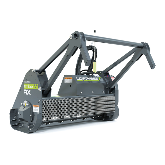
- Page 1 Timber Ax Skid-Steer Mounted Tree Shredder 63TA 73TA 83TA Owner’s Manual (Originating w/Serial Number 01-862 thru 01-903) Model Number: Serial Number: Date of Purchase: N14867_L 03.21.17...
- Page 3 The warranty policy begins upon delivery of the unit to the original customer. All Loftness products have a one (1) year warranty policy. If any Loftness product is used as a rental unit, the warranty period extends for only 30 days from the delivery date to the original customer.
-
Page 5: Table Of Contents
Table of Contents Warranty Table of Contents Introduction Owner Information ............1 Warranty Policy . - Page 6 Table of Contents Maintenance (Cont’d) Knife Replacement ............25 Knife Sharpening .
-
Page 7: Introduction
Proper operation and maintenance are essential to prevent injury or damage and to maximize machine life. The Loftness Timber Ax is an effective, reliable machine used for maintaining grass, weeds, brush and trees. It efficiently cuts and mulches up to 6" diameter material with as little as 38 hydraulic horsepower, and intermittently cuts larger diameter material. -
Page 8: Serial Number Location
Introduction Serial Number Location Manual Storage The arrow above indicates the location of the serial Keep the owner’s manual and the entire documentation number tag. packet in the storage compartment (1) provided on your Timber Ax. The owner’s manual must be available for all operators. -
Page 9: Timber Ax Features
Introduction Timber Ax Features • Standard Front Skid-Steer Mount • Rubber-Mounted Pressure Gauge • Motors Sized for 22-40 GPM • Hydraulic Hose Holder • High-Efficiency Gear-type Motor • Knife Sharpening without Detachment • Dual Cross-over Relief Valve Protection • Upward Rotor And Knife Rotation; Ridged, Pocket-style Knife Mounts •... -
Page 10: Ordering Code
Introduction Ordering Code Timber Ax (Example) The ordering code will consist of two numbers (machine size), two letters (body type), one letter (motor type), and one letter (sheaves/belt combo). An example for a Timber Ax of this type would be shown below. 63TAMP SIZE 63 = 63"... -
Page 11: Safety Instructions
See “Mandatory Shut-Down Procedure” on page 6. instructions. Contact Loftness for safety decal replacement. Timber Ax... -
Page 12: Mandatory Shut-Down Procedure
Safety Instructions Owner’s Responsibility (Cont’d) • Never attempt to make any adjustments while the engine is running or the key is in the “ON” position of the skid-steer loader. Before leaving the operator’s Make sure the attachment is installed on the machine position, disengage power to the attachment and correctly before being placed in service. - Page 13 Safety Instructions Safety Rules (Cont’d) operation. Overturning a loader without a roll bar and seatbelt can result in injury or death. Safety Instructions for Operation and • Use the handholds and step plates when getting on Maintenance (Cont’d) and off the loader to prevent falls. Keep steps and platform cleared of mud and debris.
-
Page 14: Operation Safety
Safety Instructions Safety Rules (Cont’d) • When transporting the attachment on the road at day or night, provide adequate warning to the operators of other vehicles. Operation Safety • Never park on a steep incline. Because this machine will be operated in a potentially hazardous environment, it is ABSOLUTELY MANDATORY •... -
Page 15: Hydraulic Safety
Safety Instructions Safety Rules (Cont’d) Hydraulic Safety • The hydraulic system is under high pressure. Make sure all lines and fittings are tight and in good condition. These fluids escaping under high pressure can have sufficient force to penetrate skin and cause serious injury. -
Page 16: Timber Ax Identification
Safety Instructions Timber Ax Identification Pusher Bar Hydraulic Motor and Motor Shield Skid Rotor Bearing Guard Deflector Chain Rotor and Knives Hydraulic Hoses Hydraulic Hose Support Drive Belt and Belt Shield Rotor Locking Pin Pressure Gauge (Storage Location) Mounting Plate Skid Timber Ax... -
Page 17: Safety Decal Locations
Instructions and Pressure Ratings that apply to the components used on this unit. The dealer/owner will be responsible for any damage caused by improper connection to the power unit. For technical assistance call Loftness/US Attachments at 800-828-7624 International: 320-848-6266 www.loftness.com Part No. - Page 18 Safety Instructions Safety Decal Locations (Cont’d) Part No. 4334 DANGER STAY BACK KEEP HANDS AND FEET AWAY FROM ROTATING KNIVES UNDER MACHINE WARNING DO NOT LEAVE OPERATORS POSITION WHILE POWER UNIT IS Rotor must be stabilized with the rotor locking pin RUNNING to prevent accidental rotation any time the rotor is exposed for service work.
- Page 19 MACHINE UNTIL YOU HAVE CAREFULLY READ AND THOROUGHLY UNDERSTAND THE CONTENTS OF THE OPERATOR'S MANUAL. NOTE: IF YOU DO NOT HAVE AN OPERATOR'S MANUAL, CONTACT YOUR DEALER OR LOFTNESS SPECIALIZED EQUIPMENT 650 SOUTH MAIN HECTOR, MN 55342 1-800-828-7624 FAILURE TO FOLLOW SAFETY, OPERATING, AND...
- Page 20 Timber Ax...
-
Page 21: Set-Up Instructions
Set-up Instructions Installing the Timber Ax to the Skid WARNING: Locking-wedge pins must extend Loader through the holes in attachment-mounting plate. Levers must be fully down in the locked over-center position. Failure to secure wedge Fully raise the attachment-locking levers on the loader pins can allow attachment to come off, mounting plate. -
Page 22: Checking Rotor Rotation
Set-up Instructions Checking Rotor Rotation Checking Rotor Speed NOTE: To order a Diagnostic Gauge Kit use # N16340. Raise the Timber Ax off the ground and place blocks (1) underneath the skids. Lower the Timber Ax down on the blocks. NOTE: The electronic or mechanical tachometer shown above is not supplied with the Timber Ax. -
Page 23: Pusher Bar Adjustment
Set-up Instructions Pusher Bar Adjustment Skid Adjustment Approved Lifting Device NOTE: The skid(s) can be adjusted to increase or decrease the distance between the ground and NOTE: Adjusting the pusher bar requires two people or the rotor. the use of an approved lifting device to support the push bar as it is being adjusted. -
Page 24: Rotor Locking Pin Installation
Set-up Instructions Rotor Locking Pin Installation WARNING: Do not remove the locking pin for any reason when one or more knives are missing from the rotor assembly. The WARNING: Rotor must be stabilized with imbalance could cause the rotor to turn without rotor locking pin to prevent accidental rotation warning causing serious personal injury. -
Page 25: Operating Instructions
WARNING: Do not operate the attachment above the rated RPM. Check with your Loftness dealer to be sure your attachment is set-up with the correct hydraulic motor to match the hydraulic flow GPM (Gallons Per Minute) of your machine. - Page 26 Timber Ax...
-
Page 27: Maintenance
Maintenance General Maintenance SERVICE REQUIRED To ensure efficient operation, you should inspect, lubricate, and make necessary adjustments and repairs at regular intervals. Parts that are starting to show SERVICE POINTS wear should be ordered ahead of time, before a costly breakdown occurs and you have to wait for replacement parts. -
Page 28: Lubrication
Maintenance Lubrication Grease Point Location Rotor Bearing, right Belt Tensioner, left Rotor Bearing, left Back side Back side of pusher of pusher arm shown arm shown for clarity. for clarity. Pusher Bar, left Pusher Bar, right Timber Ax... -
Page 29: Overhung Load Adapter
Maintenance Grease Points Location (Cont'd) • Rotor Bearings Grease Fittings Location: (2) Left side: Left side of the Timber Ax, at Use a #2 general purpose lithium based grease unless the base of the rear push bar arm support, noted otherwise. adjacent to the motor shield. -
Page 30: Belt Cover Removal
Maintenance Belt Cover Removal Belt Adjustment NOTE: Belt and Sheaves not shown for clarity. Loosen jam nut (1). Turn adjustment bolt (2) clockwise to increase spring tension. Turn adjustment bolt counterclockwise to decrease Remove the five bolts securing the drive belt cover (1) spring tension when replacing drive belt. -
Page 31: Knife Replacement
Maintenance Knife Replacement Knife Sharpening Insert rotor lock pin. Refer to “Rotor Locking Pin The Timber Ax knives need to be kept sharp for the Installation” on page 18. most effective operation. Sharpening intervals will vary based on usage and operator skill level. Daily inspection and touch up is recommended. -
Page 32: Knife Support Replacement
Maintenance Knife Sharpening (Cont'd) Knife Support Replacement Grind off welds. Check the cutting edge after sharpening with a square (1) to insure a continued straight cutting surface. To remove broken knife support grind off all welds. Use a knife angle gauge (2) to check for the proper angle. Adjacent knife New knife support... -
Page 33: Storage
Maintenance Knife Support Replacement (Cont'd) Storage End of Season Tack weld Tack weld • Clean entire Timber Ax thoroughly. here. here. • Clean belt and pulleys, relax the belt tension. • Lubricate all parts of the machine. See “Lubrication” on page 22. •... -
Page 34: Motor And Sheave Selection Chart
Maintenance Motor and Sheave Selection Chart MOTOR DISPLACEMENT LOFTNESS ROTOR TOP SHEAVE (LOFTNESS NUMBER) PART BOTTOM SHEAVE ( LOFTNESS NUMBER) NUMBER BELT LENGTH (LOFTNESS NUMBER) 1671 10.30" Top Sheave (N20811) 1747 62.9cc 8.00" Bottom Sheave (N20809) Muncie N10910 (3.8383ci) 63" 4B5V Belt (N28703) 1823 Model code “P”... -
Page 35: Troubleshooting
Maintenance Troubleshooting PROBLEM POSSIBLE CAUSE SOLUTION Excessive Vibration Broken or missing knife. Replace knife. Mud and/or debris wrapped around Clean the machine. the rotor. Bearing malfunction. Check and replace faulty rotor and drive line bearings. Damage to rotor (includes bent end Consult factory. - Page 36 Timber Ax...
-
Page 37: Parts Identification
Parts Identification PARTS IDENTIFICATION Timber Ax... -
Page 38: Timber Ax, Body Assembly
Parts Identification Timber Ax, Body Assembly For parts breakdown of Item 11 - Shield, see page 45. ** For parts breakdown of Item 16 - Belt Tensioner, see page 39. 16** 14 15 † When adjusting the cutter bar, † remove it completely and clean under before reinstalling. - Page 39 Parts Identification Timber Ax, Body Assembly QTY. PART # DESCRIPTION N32062 SHIELD, AXH MOTOR W/O GAUGES N18360 BOLT, 1/2" X 1-1/4" SERATED FLANGE 4304 HOSE, 15' GREASE W/FITTINGS N16472 WASHER, 1/2 NORDLOCK N28502 BOLT, 1/2" X 1-1/2" GRADE 8 N32030 TENSlONER, BELT 4 BAND N32036 COVER, TIMBER AX SHORT BELT...
-
Page 40: Body, Right Side
Parts Identification Body, Right Side Timber Ax... - Page 41 Parts Identification Body, Right Side QTY. PART # DESCRIPTION N31522 BODY, 63" TIMBER AX SHORT Not a N31519 BODY, 73" TIMBER AX SHORT replacement part. N31525 BODY, 83" TIMBER AX SHORT N20542 SKID, RIGHT ADJ AXH 3" SHORT 4055 NUT, LOCK 5/8" TOP 4386 BOLT, CARRIAGE 5/8"...
-
Page 42: Body, Left Side
Parts Identification Body, Left Side 1,2,1,3 1 2 1 3 12 10 14 1 QTY. PART # DESCRIPTION 4472 ELBOW, 1/8" 90 DEG.STREET N17007 GREASE ZERK, 1/8" NPT 4304-10 BULKHEAD, FITTING-GREASE HOSE 4386 BOLT, CARRIAGE 5/8" X 1-1/2" N32035 SKID, LEFT ADJ AXH 3" SHORT 4055 NUT, LOCK 5/8"... -
Page 43: Pusher Bar
Parts Identification Pusher Bar QTY. PART # DESCRIPTION 4960 BOLT, 3/4" X 8" GRADE 5 4287 WASHER, 3/4" LOCK N20414 BUSHING, AXH PUSHER SPACER N19048 ARM, CARBIDE PUSHER MECHANICAL 4244 BOLT, 3/4" X 4-1/2" GRADE 5 4105 GREASE-ZERK, 1/4" SCREW-IN N20100 PUSHER, 61"... -
Page 44: Rotor, With Knives
Parts Identification Rotor, with Knives To order a complete 63" rotor alloy knife kit (Items 1, 2, 3, 4), use part number N15921. To order a complete 73" rotor alloy knife kit (Items 1, 2, 3, 4), use part number N15922. To order a complete 83"... -
Page 45: Belt Tensioner (N32030)
Parts Identification Belt Tensioner (N32030) Spring length when tensioned on belt is 10.25 in. QTY. PART # DESCRIPTION N24596 ROD, THREADED 1/2 X 7.66 W/NUT N32029 BASE, BELT TIGHT SQ SLIDE 4250 NUT, STANDARD 1/2" N24211 SPRING, BELT TIGHTENER N32032 SLIDE, BELT TIGHT SQ ASSY CCH N31827 BOLT, 5/8"... -
Page 46: Motor And Sheave Options
Parts Identification Motor and Sheave Options Code P Code Q Code R Code S 10 11 10 11 12 13 14 12 Timber Ax... - Page 47 Parts Identification Motor and Sheave Options QTY. PART # DESCRIPTION N28703 BELT, 4/5VX 63 GATES N20811 SHEAVE, 4/5V X 10.30-3020 N20805 BUSHING, 1-1/2" TPL 3020 7121-03 KEY, 3/8" X 2 " N20809 SHEAVE, 4/5V X 8.0 DIA 8165 BUSHING, 2-3/16" TPL. DOD. 117715 N27290 KEY, 1/2"...
-
Page 48: Motor, Muncie
Parts Identification Motor, Muncie To order the Viton Seal Kit (not shown) for Items 12 (N49140) and 13 (N49141), use part number N49142. * For parts breakdown of Item 24 - Overhung Load Adapter, see page 44. Timber Ax... - Page 49 Parts Identification Motor, Muncie QTY. PART # DESCRIPTION N15893 CAP, 3/4 ALUMINUM HOSE N15895 CAP, 1/2 ALUMINUM HOSE 4064 WASHER, FLAT 3/8" N20038 HOSE, 3/4" X 108" HYD 5000 PSI W/O SLEEVE N15999 SLEEVE, HOSE 5.31 X 7'6" N32002 PLUG, 3/8 SCH 40 X .25 N34698 HOSE, 1/2"...
-
Page 50: Overhung Load Adapter (N16416)
Parts Identification Overhung Load Adapter (N16416) QTY. PART # DESCRIPTION N14151 SEAL, FRONT (1.50" I.D. X 2.13" O.D. X .312" THK) N14152 CUP, BEARING N14153 CONE, BEARING N14156 RING, RETAINING N14157 SEAL, REAR (55MM X 90MM X 10MM) N14158 GASKET Timber Ax... -
Page 51: Shield, Axh Motor W/O Gauges (N32062)
Parts Identification Shield, AXH Motor w/o Gauges (N32062) 5 (Assembles inside of shield) QTY. PART # DESCRIPTION 4203 BOLT, 5/16" X 1" GRADE 5 N16469 WASHER, 5/16 NORDLOCK N20198 COVER, CARBIDE MOTOR SHIELD HOLE N32063 SHIELD, AXH MOTOR W/O GAUGES N20753 FLANGE, AXH MOTOR SHIELD 4237... -
Page 52: Gauge
Parts Identification Gauge QTY. PART # DESCRIPTION N16132 BOLT, BHCS #8-32 X 1 N16163 GAUGE, 0-6000 PSI 4" PRESS N16333 BOLT, BHCS #10-32 X 1 N16332 FLANGE, MOUNT GAUGE N16331 FLANGE, MOUNT GAUGE #8 N16133 NUT, NYLON INSERT #8 N16335 FLANGE, MOUNT #10 N16334 NUT, NYLON INSERT #10... -
Page 53: Holder, Hose Stick And Chain (N20403)
Parts Identification Holder, Hose Stick and Chain (N20403) QTY. PART # DESCRIPTION N15956 HOLDER, HOSE WITH EXTRA HOLES N15939 PROTECTOR, RUBBER 3" HOSE N15938 CLAMP, 3-1/2" HOSE N20218 CHAIN, HOSE SUPPORT 4-LINK N15247 LINK, 1/4" CHAIN CONNECTOR Timber Ax Timber Ax... -
Page 54: Machine Decals And Signs
AND THOROUGHLY UNDERSTAND THE CONTENTS OF THE OPERATOR'S MANUAL. NOTE: IF YOU DO NOT HAVE AN OPERATOR'S Part No. N17013 MANUAL, CONTACT YOUR DEALER OR LOFTNESS SPECIALIZED EQUIPMENT WARNING 650 SOUTH MAIN HECTOR, MN 55342 1-800-828-7624 Due to the possible danger of flying debris,... - Page 55 Instructions and Pressure Ratings that apply to the components used on this unit. The dealer/owner will be responsible for any damage caused by improper connection to the power unit. For technical assistance call Loftness/US Attachments at 800-828-7624 International: 320-848-6266 www.loftness.com Part No.
- Page 56 Parts Identification Machine Decals and Signs (Cont’d) Part No. N28526 Part No. N13517 Part No. N28525 Part No. N26973 Part No. N13872 Part No. N28576 Timber Ax...
-
Page 57: Appendix
Appendix Specifications DESCRIPTION TIMBER AX Cutting Width 63 in. (160.02 cm) 73 in. (185.42 cm) 83 in. (210.82 cm) Operating Capacity 6 in. (15.2 cm) Continuous Intermittently cuts larger diameter material Capacity Monitor Pressure Gauge Motor Fixed Displacement Rotor Bearing 2.1875 in. -
Page 58: Dimensions
Appendix Dimensions Timber Ax DESCRIPTION Cutting Width (C) 63 in. (160.02 cm) 73 in. (185.42 cm) 83 in. (210.82 cm) Overall Width (D) 81.19 in. (206.20 cm) 91.19 in. (231.62 cm) 101.19 in. (257.02 cm) Operating Height (A) 35.75 in. (90.81 cm) 35.75 in. -
Page 59: Torque Specifications
Appendix Torque Specifications Inches Hardware and Lock Nuts TORQUE CHARTS Minimum Hardware Tightening Torques Normal Assembly Applications (Standard Hardware and Lock Nuts) Nominal Unplated Plated Unplated Plated Unplated Plated Grade Grade Size W / ZnCr W / ZnCr W / ZnCr W / Gr. -
Page 60: Metric Hardware And Lock Nuts
Appendix Torque Specifications (Cont’d) Metric Hardware and Lock Nuts TORQUE CHARTS Minimum Hardware Tightening Torques Normal Assembly Applications (Metric Hardware and Lock Nuts) Class 5,8 Class 8,8 Class 10,9 Lock nuts Nominal Unplated Plated Unplated Plated Unplated Plated Class 8 Size W / ZnCr W / ZnCr... - Page 62 Loftness Specialized Equipment, Inc. 650 So. Main Street • PO Box 337 • Hector, MN 55342 Tel: 320.848.6266 • Fax: 320.848.6269 • Toll Free: 1.800.828.7624 Printed in USA © Loftness 2017...
Need help?
Do you have a question about the Timber Ax 63TA and is the answer not in the manual?
Questions and answers