
Related Manuals for LOFTNESS Battle Ax 50 Series


Summary of Contents for LOFTNESS Battle Ax 50 Series
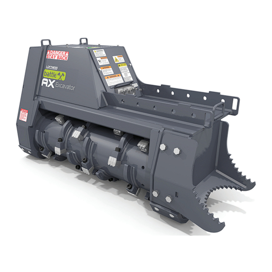
- Page 1 Battle Ax Excavator Mulching Head 50 Series Owner’s Manual and Parts Book (Originating w/Serial Number 103-101) Model Number: Serial Number: Date of Purchase: 207822 Rev. A 06.30.20...
- Page 3 All Loftness products have a one (1) year limited warranty. The XLB10 Grain Bag Loader has a two (2) year limited warranty. If any Loftness product is used as rental equipment the limited warranty period is for only 30 days from the delivery date to the original customers.
-
Page 5: Table Of Contents
Battle Ax 50 Series (Example) ........ - Page 6 Battle Ax 50 Series, Complete ........
-
Page 7: Ordering Code
Ordering Code Ordering Code Battle Ax 50 Series (Example) The ordering code will consist of two numbers (machine size), two letters (machine type), two numbers (series), one letter (cutter type), two numbers (motor system), one letter (sprocket/belt combo), and one letter (options). - Page 8 Battle Ax OM...
-
Page 9: Introduction
The Loftness Battle Ax is an effective, reliable machine used for maintaining grass, weeds, brush and trees. For best results, operate the machine as low to the ground as possible without the teeth striking ground or other obstructions. -
Page 10: Battle Ax Features
Introduction Battle Ax Features • Hydraulic Driven. • 68 mm Synchronous Belt. • Built-in Depth Gauges - controls cutting depth. • Two-stage Cutting Chamber - uses 2 shear bars, producing a finer mulch with less passes. • Triple Carbide Teeth. •... -
Page 11: Safety Instructions
Safety First Be certain all machine operators are aware of the dangers indicated by safety decals applied to the machine, and be certain they follow all safety decal Safety Alert Symbol instructions. Contact Loftness for safety decal replacement. This message alert... -
Page 12: Mandatory Shut-Down Procedure
Safety Instructions Mandatory Shut-Down Procedure • Always have an operator in the machine while the attachment is in operation. Never leave the machine and attachment running and unattended. • Stop the machine and attachment on a level surface and lower the attachment to the ground. •... -
Page 13: Hydraulic Safety
Safety Instructions Safety Rules (Cont’d) • Know the area before operating the machine. Be aware of power lines or other equipment. • Make sure the operator’s area is clear of any • Do not lubricate parts while the machine is running. distracting objects. -
Page 14: Safety Decal Locations
Safety Instructions Safety Decal Locations Check and replace any worn, torn, hard to read or missing safety decals on your machine. NOTE: This section shows where safety-related decals are applied on the machine. For all machine decals see “Machine Decals and Signs” on page 38. See the following page for detailed images of the safety decals called out above. - Page 15 Safety Instructions Safety Decal Locations (Cont’d) WARNING IMPROPER CONNECTION TO THE POWER UNIT’S HYDRAULIC SYSTEM COULD CAUSE SERIOUS COMPONENT DAMAGE AND PERSONAL INJURY. This attachment can be configured with different components to operate on a variety of power units. Part No. 4334 It is absolutely MANDATORY that you refer to your OPERATOR’S MANUAL for Set-up Instructions and Pressure Ratings that apply to the components used on this unit.
-
Page 16: Battle Ax Identification
Safety Instructions Battle Ax Identification Manual Holder Drive Sheave Access Covers Drive Belt Rotor Sheave Skid Drive Belt Cover Cutting Teeth Rotor Skid Top Motor Cover Hydraulic Hose Connections Mounting Plate Hydraulic Motor Compartment Hook Shipping Stand Deflector Chains Shipping Stand Battle Ax OM... -
Page 17: Set-Up Instructions
Mounting the Battle Ax to the Excavator For a mounting bracket specific to your model of Do not cap Case excavator, contact Loftness. Drain Protection. NOTE: Make sure hydraulic hoses are connected to the Tank Battle Ax before installing the mounting bracket. -
Page 18: Remove Shipping Stands
Set-up Instructions Remove Shipping Stands Checking Rotor Rotation DANGER: Keep hands, feet, and clothing clear of rotor and bearings while excavator is running. Stands (1) are secured to the Battle Ax to keep it stable during shipping. These can be removed after the unit is initially mounted to the excavator. -
Page 19: Checking Rotor Speed
Set-up Instructions Checking Rotor Speed Adjusting Rotor RPM NOTE: Motor is preset at the factory to maximum DANGER: Shut down power from the displacement. Motor displacement must be excavator before removing the bearing cover adjusted on the cutter head to achieve the and applying reflective tape to rotor shaft end. - Page 20 Set-up Instructions Adjusting Rotor RPM (Cont’d) Remove the covers (1) on the adjustment screws. To INCREASE ROTOR RPM: Turn bottom adjustment screw (2) out using the 8 mm Allen wrench. Loosen jam nut (4) using a 24 mm wrench. Turn top adjustment screw (3) in using a 8 mm Allen wrench.
-
Page 21: Operating Instructions
RPM. Check with your When mulching large trees, work from the top down. Loftness dealer to be sure your attachment is In wet conditions, operate at a slower speed and set-up with the correct hydraulic motor to... -
Page 22: Detaching Battle Ax
Operating Instructions Detaching Battle Ax Park excavator on a dry level surface. Turn power off to the Battle Ax and install shipping stands. See “Remove Shipping Stands” on page 12 for reference. Lower the Battle Ax to the ground. Shut off engine and remove key. Disconnect hydraulic hoses. -
Page 23: Maintenance
Maintenance General Maintenance Lubrication To ensure efficient operation, you should inspect, Grease Points Location lubricate, and make necessary adjustments and repairs at regular intervals. Parts that are starting to show Use a #2 general purpose lithium based grease unless wear should be ordered ahead of time, before a costly noted otherwise. -
Page 24: Overhung Load Adapter
Maintenance Lubrication (Cont’d) Removing Belt Cover and Access Covers Grease Points Location (Cont’d) DANGER: Shut down and lock out power from the excavator before removing the belt cover or access covers. Failure to do so could result in serious injury or death. Location: Hook end rotor bearing (2). -
Page 25: Removing Top Motor Cover
Maintenance Removing Top Motor Cover Removing Hook DANGER: Shut down and lock out power DANGER: Shut down and lock out power from the excavator before removing the top from the excavator before removing the motor cover. Failure to do so could result in hook. -
Page 26: Tooth Removal And Installation
Maintenance Tooth Removal and Installation Adjusting Belt Tension DANGER: Shut down and lock out power from the excavator before removing and installing any cutting teeth. Failure to do so could result in serious injury or death. Slightly loosen the four overhung load adapter (OHLA) support bolts (1). -
Page 27: Replacing Belt
Maintenance Replacing Belt Remove the three screws (1) from the taper lock bushing (2) of the sprocket (3). To replace the belt, follow the procedures for “Belt Insert two of the screws into the threaded holes (4). Tension Adjustment” preceding this subsection and decrease the belt tension additionally to allow the belt to Tighten the two screws until bushing grip is released. -
Page 28: Skid Removal/Replacement
Maintenance Skid Removal/Replacement Cutter Bar Adjustment and Replacement WARNING: Shut down and lock out power from the excavator before removing skids. Lift the Battle Ax off of the ground about 6 inches. Place blocks under the rotor (not under teeth) to support the shredder when lowered. -
Page 29: Storage
Maintenance Storage End of Season • Clean entire Battle Ax thoroughly. • Lubricate all parts of the machine. See “Lubrication” on page 17. • Make a list of all worn or damaged parts and replace them. • Paint all parts that are worn or rusted. •... -
Page 30: Troubleshooting
Maintenance Troubleshooting PROBLEM CAUSE SOLUTION Excessive vibration. Broken or missing teeth. Replace teeth. Mud and/or debris wrapped around Clean the Battle Ax. the rotor. Faulty rotor bearing. Replace bearing(s). Damage to rotor (includes bent end Consult factory. of shafts, missing balance weights, or actual rotor deformity from striking rocks, etc.) Uneven cutting. -
Page 31: Parts Identification
Parts Identification PARTS IDENTIFICATION Battle Ax OM... -
Page 32: Battle Ax 50 Series, Complete
Parts Identification Battle Ax 50 Series, Complete Detailed parts breakdowns of the assemblies (items) are listed on the following pages: Item 1 - Belt Assembly (207567) - See page 33. Item 2 - Motor Assembly (207534)- See page 34. Item 3 - Rotor Assembly (207485) - See page 32. - Page 33 Parts Identification Battle Ax 50 Series, Complete QTY. PART # DESCRIPTION 207567 BELT ASSEMBLY, 71T 71B 68MM 207534 MOTOR ASSEMBLY, LINDE 165CC 207485 ROTOR ASSEMBLY, 51" BATTLE AX Battle Ax OM...
-
Page 34: Covers, Skid Shoes, Hook, And Hitch Mount
Parts Identification Covers, Skid Shoes, Hook, and Hitch Mount Battle Ax OM... - Page 35 Parts Identification Covers, Skid Shoes, Hook, and Hitch Mount QTY. PART # DESCRIPTION 207568 COVER, MOTOR W/DECALS N18360 BOLT,1/2-13 X 1-1/4 SER FLG 207585 COVER, BELT W/STIFFENER N21261 PLATE, COVER LIFT/INSPECTION 4056 NUT, LOCK 3/4" 4993 BOLT, CARRIAGE 3/4" X 2-1/2" 207580 PLATE, SKID W/BRACE 207507...
-
Page 36: Cutter Bar, Deflector Chains, And Manual Holder
Parts Identification Cutter Bar, Deflector Chains, and Manual Holder 14,15 4 (See Detail A for location.) Detail A Item 4 (Cutter Bar) location. Battle Ax OM... - Page 37 WASHER, 1/2" FLAT 4015 BOLT, 1/2" X 2" GRADE 5 N17007 GREASEZERK, 1/8" NPT 4304-10 BULKHEAD, FITTING-GREASE HOSE 4340 BOLT, 1/4" X 3/4" GRADE 5 N19600 HOLDER, 01-315A STND. MANUAL 207822 BATTLE AX 50 SERIES MANUAL (not shown) Battle Ax OM...
-
Page 38: Rotor Assembly, 51" Battle Ax (207485)
Parts Identification Rotor Assembly, 51" Battle Ax (207485) QTY. PART # DESCRIPTION 4304 HOSE, GREASE 1/8" X 15" 4471 ELBOW, 1/8" 45 DEG.STREET 4306 BOLT, 5/8" X 3" GR 8 FN TH N16473 WASHER, 5/8 NORDLOCK N16418 BEARING,3" PILOT FLNG ROLLER 4343 BOLT, 3/4"... -
Page 39: Belt Assembly, 71T 71B 68Mm (207567)
Parts Identification Belt Assembly, 71T 71B 68MM (207567) QTY. PART # DESCRIPTION 200299 SPROCKET, 14MM 71 TOOTH 68MM 200864 BUSHING, TAPERLOCK 2.25 3525 7122-06 KEY, 1/2" X 2-1/2" N28529 BOLT, SHCS 1/2" X 1-1/2" 207566 BELT, POLY CHAIN 14MM 2380 X 68 200865 KEY, 3/4 X 2-1/2 200363... -
Page 40: Motor Assembly, Linde 165Cc (207534)
Parts Identification Motor Assembly, Linde 165cc (207534) 15** 20,21 24,25 † 27,28 24,25 * For parts breakdown of item 7, Overhung Load Adapter (200937), see page 36. ** For parts breakdown of item 15, Motor (200460), see page 37. † For parts breakdown of item 26, Plug (27575), see page 37. Battle Ax OM... - Page 41 Parts Identification Motor Assembly, Linde 165cc (207534) QTY. PART # DESCRIPTION 4224 BOLT, 3/4" X 2-1/2" GRADE 5 N16474 WASHER, 3/4 NORDLOCK 200843 PLATE, COVER 200872 BRACKET, TENSIONER 4201 BOLT, 1/2" X 4-1/2" GR 5 N13997 BOLT, 3/4" X 1-3/4" GRADE 5 200937 OHLA, ASSEMBLED N28567...
-
Page 42: Overhung Load Adapter (200937)
Parts Identification Overhung Load Adapter (200937) QTY. PART # DESCRIPTION 200941 BOLT, SHCS 3/4-10 X 1-1/2 200940 BOLT, SHCS 1/4-20 X 1/2 200935 PLATE, SEAL REAR N28457 SEAL, REAR 2.25 X 3.50 X .438 N143011 BEARING, SPHERICAL 80MM 4107 GREASE-ZERK, 1/4" SCREW-IN 90 DEG 200934 SHAFT, OHLA SPLINE 200942... -
Page 43: Motor, 165Cc Adjustable, Linde (200460)
Parts Identification Motor, 165cc Adjustable, Linde (200460) QTY. PART # DESCRIPTION 200507 SEAL KIT, SHAFT (Includes items 1, 2 and 3) – SHIM 60X72X1.50-ST 200506 SHAFT SEAL DAS 55X72X7-V80 WN 17216 – O-RINGS Manifold, Check 132GPM 6000PSI (207575) QTY. PART # DESCRIPTION 207577 CHECK, 132GPM... -
Page 44: Machine Decals And Signs
Parts Identification Machine Decals and Signs Part No. N28386 DANGER NOTE: All safety related decals are also shown in the Safety Instructions Section along with their STAY BACK location on the machine. See “Safety Decal KEEP HANDS AND FEET Locations” on page 8. AWAY FROM ROTATING KNIVES UNDER MACHINE DO NOT LEAVE... - Page 45 Parts Identification Machine Decals and Signs (Cont’d) Part No. N28010 Part No. N33105 Part No. 203264 Part No. N13517 Part No. 4138 Part No. 200490 Part No. N13721 Part No. 207851 CASE DRAIN PROTECTION Part No. N49280 - (Large) DO NOT CAP 207851 Part No.
- Page 46 Battle Ax OM...
-
Page 47: Appendix
Appendix Specifications DESCRIPTION BATTLE AX Cutting Width 51 in. (129.5 cm) Motor Adjustable Displacement Piston Motor 165cc Rotor Bearing 3.0 in. Piloted Double Taper Rotor Tip Diameter 21 in. (53.34 cm) Sprockets Taperlock Belt 68 mm Synchronous Belt Mount Excavator Make/Model Specific Shear Bar Standard Cutters... -
Page 48: Dimensions
Appendix Dimensions DESCRIPTION BATTLE AX Cutting Path (A) 51 in. (129.5 cm) Overall Length (B) 85.5 in. (217.2 cm) Overall Width (C) 33.5 in. (85.0 cm) Overall Height (D) 46.5 in. (118.1 cm) Number Of Teeth Weight (without mount) 4,200 lbs. (1905.1 kg) Crated Weight 4,350 lbs. -
Page 49: Torque Specifications
Appendix Torque Specifications Inches Hardware and Lock Nuts Battle Ax OM... -
Page 50: Metric Hardware And Lock Nuts
Appendix Torque Specifications (Cont’d) Metric Hardware and Lock Nuts Battle Ax OM... - Page 52 Loftness Specialized Equipment, Inc. 650 So. Main Street • PO Box 337 • Hector, MN 55342 Tel: 320.848.6266 • Fax: 320.848.6269 • Toll Free: 1.800.828.7624 Printed in USA © Loftness 2020...
Need help?
Do you have a question about the Battle Ax 50 Series and is the answer not in the manual?
Questions and answers