Advertisement
Quick Links
SMARTMETER
PORTABLE TEMPERATURE METER - INSTRUCTIONS MANUAL – V1.0x
1 INTRODUCTION
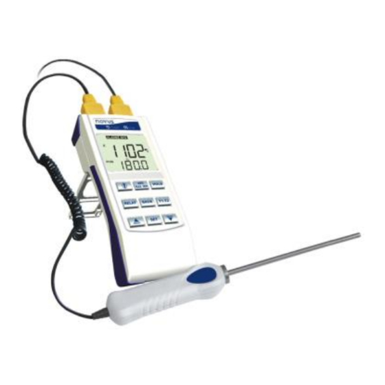
SmartMeter is a portable temperature meter with high-contrast LCD.
The Smart Meter housing enables industrial environment or bench-
top operation and provides a belt carrying fixture. It supports 2
temperature sensors with independent and concurrent display of
measured values. It provides the capability of reading 0-50 mV
electric signals with configurable indication scale.
Difference between channels, relative measure, minimum, maximum
and average values, hold and alarm functions are also available. It
also features an auto power off resource in case the device is idle, in
order to extend battery life.
The device is supplied with a K-type thermocouple with 1.5 m cable.
1.1 UNPACKING
The meter is supplied in proper packaging that offers suitable
protection during transit and storage. Unpack with care. Upon
delivery, make sure that there is no damage to the instrument, and
that there are no missing items.
Within packaging, you should find, besides the manual, the meter
and a K-type thermocouple sensor.
2 SPECIFICATIONS
Input types and max. indication range
J thermocouple .......................................................... - 100 to 760 ºC
K thermocouple....................................................... - 150 to 1.370 ºC
T thermocouple .......................................................... - 160 to 400 ºC
E thermocouple............................................................. -90 to 720 ºC
N thermocouple ...................................................... - 270 to 1,300 ºC
R thermocouple ........................................................ - 50 to 1,760 ºC
S thermocouple......................................................... - 50 to 1,760 ºC
B thermocouple......................................................... 500 to 1,820 ºC
Pt100 ......................................................................... - 200 to 600 ºC
Voltage 0-50 mV ................................... - 1,999 to 9,999 (Adjustable)
All input types are factory calibrated. NBR 12771, Pt100 NBR
13773/97 (IEC-751) (385) calibrated thermocouples.
Thermocouples: .............................. 0.25 % F.S. 1 ºC
Accuracy:
Pt100: ............................................... 0.2 % F.S. 1 ºC
0-50 mV: ........................................ 0.2 % F.S. 1 digit
Resolution: ...................................................................................... 0.1 ºC
Sampling rate: ............................................................ 2 timer per second
Input impedance: ............................... > 10 MΩ (Thermocouples, 50 mV)
Pt100 excitation current: ............................................................ 0.165 mA
Power supply: ...................................................................... 9 Vdc battery
AC / DC adapter ............................................................................. 6 Vdc
Estimated autonomy: .................................... 400 hours (alkaline battery)
Dimensions: ................................................................. 165 x 73 x 36 mm
Weight: ............................................................................................ 205 g
: .......................................................................................... IP40
Protection
3 CONNECTIONS
Female input connectors suitable for RTD / TC compensated
connectors, as shown below.
Figure 01 — Meter supported connectors
Only two input terminals are used to connect thermocouples. Input
terminals have different size holes, which prevent inappropriate
installations.
Figure 02 — Thermocouple connection
All three terminals are used for Pt100 (RTD)
Figure 03 – Pt100 connectors sensors
The Pt100 internal connections should be made as shown in figure
below.
Figure 04 — Internal connections of Pt100 sensors
For the 0-50 mV signal, installation should comply with the following
connections:
Figure 05 — 0-50 signal connection
Advertisement

Subscribe to Our Youtube Channel
Related Manuals for scigiene SMARTMETER


Summary of Contents for scigiene SMARTMETER
- Page 1 PORTABLE TEMPERATURE METER - INSTRUCTIONS MANUAL – V1.0x 1 INTRODUCTION 3 CONNECTIONS SmartMeter is a portable temperature meter with high-contrast LCD. Female input connectors suitable for RTD / TC compensated The Smart Meter housing enables industrial environment or bench- connectors, as shown below.
- Page 2 In each channel there can be two indication values, when they are reached the audible alarm is triggered. A Figure 07 — SmartMeter display visual indicator is also displayed in the meter when the indication is under an alarm condition.
- Page 3 SmartMeter sensor. The offset can be of 10 % of the selected sensor maximum range, upwards or downwards. CONFIGURATION CYCLE (Indication Offset, channel 2) 0fs.2 To enter the configuration cycle, press . The meter BACK displays typ.1, the first parameter of the cycle. To access the Allows for an offset in the temperature value displayed in channel 2.
- Page 4 SmartMeter 6 WARRANTY alibration Channel 2) L(.(2 INPUT OFFSET CALIBRATION: Adjusts the lowest limit of the input The manufacturer products are covered by a 12-month warranty signal indication range (offset). In order to change the indicated provided the purchaser presents the sales receipt and the following value, it may be required to press several times.
Need help?
Do you have a question about the SMARTMETER and is the answer not in the manual?
Questions and answers