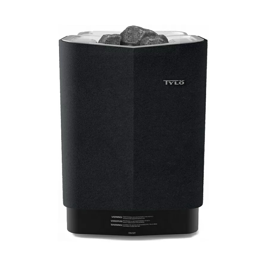
Tylo Sense Combi Pure Installation Manual
Hide thumbs
Also See for Sense Combi Pure:
- User manual (46 pages) ,
- Installation manual (59 pages) ,
- Installation manual (66 pages)
Advertisement
Quick Links
Advertisement

Summary of Contents for Tylo Sense Combi Pure
- Page 1 Pure/Elite...
- Page 2 WARNING! • Poor ventilation or heater positioning may lead to dry distillation, posing a re risk under certain circum- stances! • Insu cient insulation of the sauna cabin may pose a re risk! • Use of the wrong materials in the sauna cabin, such as particle board, drywall, etc., may pose a re risk! •...
- Page 3 NOTE! A brick wall without heat insulation increases the warm-up time. Each square meter of plastered ceiling or wall surface equals an additional 1.2–2 m³ of sauna volume. Table 1: Output and sauna volume DANGER! Poor ventilation or heater positioning may lead to dry distillation, posing a re risk Figure 1: Sauna heater/control panel parts under certain circumstances!
- Page 4 Figure 2: Schematic diagram of installation Figure 4: Sensor installation on ceiling on centreline of heater as seen from the front and side DANGER! No more than one heater may be instal- led in the same sauna cabin. Figure 5: Positioning the heater - recess installation Figure 3: Positioning the heater - normal installation...
- Page 5 DANGER! The air exhaust vent must not lead out- doors. This could cause the ventilation direction to be reversed, which may negatively a ect the heater temperature cut-out. DANGER! Any gap above the sauna ceiling should not be sealed without leaving at least one vent hole on the same wall as the sauna door! Figure 6: Safety distance, control panel Figure 7: Positioning the air intake and exhaust vents...
- Page 6 Combi Pure: Combi Elite: Figure 9: Opening/closing the cover WARNING! Always check that the heater is con- nected to the correct main/phase voltage! Figure 11: Hang the heater up. Fig 12: Fit spacers Figure 10: Circuit board...
- Page 7 Figure 16A: Wiring through the wall. The example shows the sensor for Combi Pure. Fig 13: Fitting the cover for the water reservoir, herb grille and fragrance holder/air humidi er Combi Pure Fig 16B: Wiring through the wall. The example shows the sensor for Combi Elite.
- Page 8 6,6-8,0 kW 6,6-8,0-10,5 kW 6,6-8,0-10,5 kW * ** RJ10 4P4C 3 x 0.75 mm 200-240 V 1N~/2~ 200-230 V 3~ 400-415 V 3N~ RJ10 4P4C RJ10 4P4C RJ10 4P4C Combi Elite - max 30m Combi Pure - max 100m Figure 17: Wiring diagram 3:12V 4:GND 1 2 3 4...
- Page 9 Pos 1. Pos 2. Pos 3. Pos 4. Pos 5. Ext sw Door sw Bim/NTC Addon (option) Pin 1: Pin 1: Pin 1: Pin 1: Bim Pin: Pin 2: NTC Pin 2: LED Pin 2: LED Pin 2: NTC Pin 3: NTC Pin 3: SW Pin 3: SW Pin 3: NTC...


Need help?
Do you have a question about the Sense Combi Pure and is the answer not in the manual?
Questions and answers