
Related Manuals for JR X9303 2.4


Summary of Contents for JR X9303 2.4
- Page 1 X9303 2.4 9-CHANNEL COMPUTER RADIO SYSTEM WITH SPEKTRUM 2.4GHz DSM TECHNOLOGY INSTRUCTION AND PROGRAMMING MANUAL...
- Page 2 Battery Charging ...........................G-12 Transmitter/Receiver ............................G-12 JR Transmitter Charging ...........................G-12 Using the Included Charger ........................G-12 X9303 2.4 Transmitter Features (Mode 2 Airplane Shown) ..........G-13 X9303 2.4 Transmitter Features (Rear) ...................G-14 Battery Cover ............................G-14 X9303 2.4 Transmitter Features (Internal) ................G-15 Control Stick Tension Adjustment ......................G-15 Back of Transmitter (Mode 2) ........................G-15...
- Page 3 Standard Range Testing ........................G-21 Range Testing the X9303 2.4 ........................G-21 Advanced Range Testing Using a Flight Log ................G-22 Advanced Range Testing the X9303 2.4 ....................G-22 Flight Log—Optional for JR R921 Receiver ................G-23 Using the Flight Log ..........................G-23 Receiver Power System Requirements ..................G-24 Recommended Power System Guidelines ....................G-24...
- Page 4 TRANSFER – TRANSFER THE MODEL TO ANOTHER TRANSMITTER OR TO DATASAFE ..H-7 TRANSFER A MODEL FROM THE X9303 2.4 – (Transfer function) – To Send ......H-7 TRANSFER A MODEL TO THE X9303 2.4 – (Transfer function) – To Receive ....... H-8...
- Page 5 REVO.MIX/Revo Mix Function: Non Heading Lock Gyros Only ............H-27 GYRO SENS/Gyro Gain Function ......................H-28 Accessing the Gyro Gain Function .......................H-28 Gyro Remote Gain Connections: JR G500T, JR770 and Others ........... H-29 Remote Gain Gyros .............................H-29 Mixing – Cyclic-to-Throttle Mixing ......................H-29 Rudder-to-Throttle Mixing .........................H-30...
- Page 6 MULTI-POINT MIXES – Example: FMOD to Gear Mixing (Retract and other Functions) ..H-41 Trainer – Programmable Trainer System....................H-44 X9303 2.4 USED AS MASTER (INSTRUCTOR) – (Trainer System) ..........H-44 X9303 2.4 USED AS SLAVE (STUDENT) – (Trainer System) ............H-45 Timer –...
- Page 7 PROG MIX - PROGRAMMABLE MIXERS ....................S-29 MULTI-POINT PROGRAMMABLE MIXER ..................... S-33 Trainer – Programmable Trainer System....................S-36 X9303 2.4 USED AS MASTER (INSTRUCTOR) – (Trainer System) ..........S-36 X9303 2.4 USED AS SLAVE (STUDENT) – (Trainer System) ............S-37 Timer ................................S-37 Monitor ................................
- Page 8 Step #24 Dual Rate and Exponential ......................S-56 Step #25 Elevator-to-Flap Mix ........................S-57 Step #26 Aileron-to-Flap ..........................S-58 Step #27 Aileron Differential ........................S-58 Flap Rate ..............................S-59 Flaperon Mix ............................... S-59 Step #28 Flap Rate, Camber Mix and Camber Adjust ................S-59 Step #29 Flap Rate, Camber Mix and Camber Adjust (continued) ............
-
Page 9: Section 1: Using The Manual
A blank data sheet has been included at the end of transmitter features and specifications plus information each section, as well as on the JR web site. Once all on the included components and accessories. Guidelines data has been input for a particular model, it is highly for receiver and servo installation are also included. - Page 10 AR7000 7-channel full-range receiver AR9000 9-channel full-range receiver Important: When using the X9303 2.4 with parkflyer receivers (the AR6000 and AR6100), it’s imperative that these receivers only be flown in parkflyer-type aircraft (small electric airplanes or mini and micro helicopters). Flying receivers designed for parkflyers in larger aircraft could cause loss of control.
-
Page 11: Section 3: Component Specifications
Section 3: Component Specifications Servo Specifications Type DS821 Torque 72 oz/in Speed Weight 1.5 oz Size (in) (L x W x H) .74x1.50x1.47 Ball Bearing Motor 3-pole Ferrite Charger Specifications Model Number AD35M05 Input Voltage AC 120V, 60Hz Output Current 11.6V Tx/110mAh, 5.8V Rx/110mAh Charging Time 15 hours... -
Page 12: Battery Charging
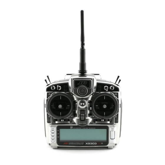
Beware of CHARGER PIGTAIL FOR RECEIVER Do not use the charger for equipment other than JR. The improper connections based on “color-coded” wire leads, charging plug polarity may not be the same. Equipment as they may not apply in this instance. - Page 13 X9303 2.4 Transmitter Features (Mode 2 Airplane Shown) Mix Switch AUX2 Aileron Elevator AUX4/ Dual Rate Dual Rate Rudder Dual Aux Trim Rate Gear Switch Flap Trim Trainer Button Flap Switch Lever Lever Throttle/ Elevator/ Rudder Stick Aileron Stick Throttle Trim...
-
Page 14: Battery Cover
X9303 2.4 Transmitter Features (Rear) Model No. X9303 FCC ID: BRWDAMTX10 IC: 6157 A-BRWDAMT HORIZON HOBBY, INC. MADE IN JAPAN Battery Cover CAUTION: THE BATTERY CONNECTION IS KEYED SO THAT IT CAN ONLY BE PLUGGED IN ONE DIRECTION. DO NOT FORCE. -
Page 15: Control Stick Tension Adjustment
X9303 2.4 Transmitter Features (Internal) AILERON TENSION SCREW THROTTLE TENSION SCREW ELEVATOR TENSION SCREW RUDDER TENSION SCREW Back of Transmitter (Mode 2) Control Stick Tension Adjustment Remove the six transmitter screws from the back cover as Adjust each gimbal tension screw for desired tension shown on page G-14. -
Page 16: Advanced Digital Trims
JRPA045). These stick ends are crafted from bar stock aluminum, and are available at your local JR dealer. Neckstrap Attachment An eyelet is provided on the face of the X9303 2.4 transmitter that allows you to connect a Neck Strap (JRPA023). G-16... -
Page 17: Installing The Receiver
(jets) in the top turtle deck and even in the tail. The optimum location is as far away from any conductive materials as practical. Note: The JR R921 requires that at least one remote receiver be used. Install the main receiver using the same method you would use to install a conventional receiver in your aircraft. -
Page 18: Model Match
Rubber Grommet Brass Eyelet Model Match The X9303 2.4 features patented ModelMatch technology that prevents the operation of a model if the wrong model memory is selected. During binding, the receiver actually learns and remembers the specific model memory (1 thru 30) that the transmitter is currently programmed to. - Page 19 During binding, the servo’s fail-safe positions are stored. The following sequence describes the binding procedure for the JR R921, however, all JR and Spektrum DSM aircraft receivers are bound in the same way. How To Bind 1. With the system hooked up as shown, insert the bind plug in the charge plug receptacle.
-
Page 20: Fail-Safe Functions
In glow-powered The JR R921 receiver features two types of fail-safe: models, the throttle servo has no input so it remains in its SmartSafe and Preset Fail-safe. - Page 21 Range Testing the X9303 2.4 3. You should have total control of the model with the button depressed at 30 paces (90 feet). 4. If control issues exist, call the JR Service Center at 1-877-504-0233 for further assistance. G-21...
-
Page 22: Advanced Range Testing Using A Flight Log
Advanced Range Testing the X9303 2.4 range check will have recorded zero frame losses. 1. Plug a flight log (optional) into the data port in the JR Scrolling the Flight Log through the Antenna fades R921 receiver and turn on the system (transmitter and (A, B, L, R) allow you to evaluate the performance receiver). - Page 23 A hold occurs when 45 continuous (one right after the other) frame losses occur. The Flight Log is compatible with JR R921 receivers. The Flight Log displays overall RF link performance as well This takes about one second. If a hold occurs during a as the individual internal and external receiver link data.
-
Page 24: Receiver Power System Requirements
Receiver Power System Requirements With all radio installations, it is vital that the onboard 2. With the current meter inline with the receiver battery power system provides adequate power without lead, load the control surfaces (apply pressure interruption to the receiver even when the system is fully with your hand) while monitoring the current. -
Page 25: Flash Memory
Flash Memory All preprogrammed data is protected by a flash memory that guards against memory loss main transmitter battery failure. Battery Alarm and Display When the transmitter voltage drops below 9.0 volts DC, the display flashes “BATT LOW” and an alarm sounds. If you are flying when this occurs, land immediately. - Page 26 3.5-volt threshold, causing and Spektrum transmitters is highly advised against. the entire system (servos and receiver) to brown The X9303 2.4 system will operate for over 15 hours out. When the voltage drops below the low voltage using a 2700mAh Ni-MH battery.
Need help?
Do you have a question about the X9303 2.4 and is the answer not in the manual?
Questions and answers